6. Buildroot Application
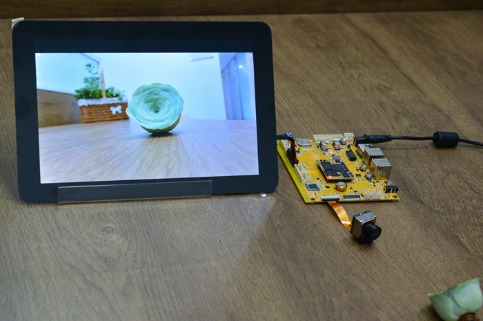
6.1 Display(MIPI)
Connect the board and 10.1-inch MIPI LCD, MIPI Camera, then start up. After the system boot, the LCD will display the preview of camera.
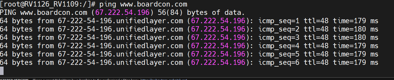
6.2 Ethernet
Connect the Board and router with an Ethernet cable (default DHCP=Yes). User can ping URL/IP at terminal.
udhcpc                 // get IP
ifconfig
ping www.boardcon.com
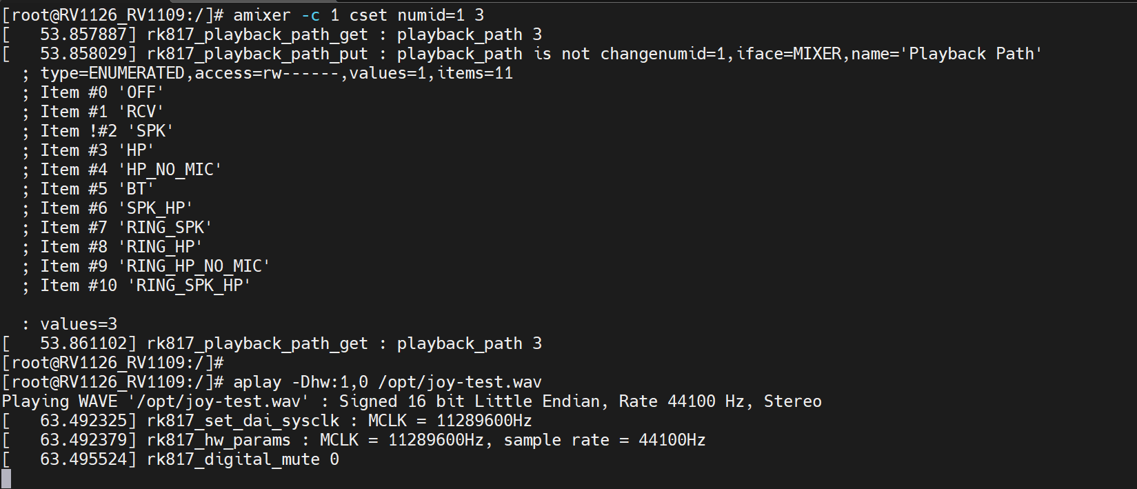
6.3 Audio Player
Copy Audio files to SDcard/U-disk then insert it to the board. After system boot execute follow command to play.
amixer -c 1 cset numid=1 3
aplay -Dhw:1,0 /opt/joy-test.wav
6.4 Record
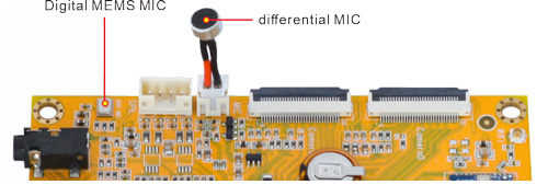
arecord -l // List-devices
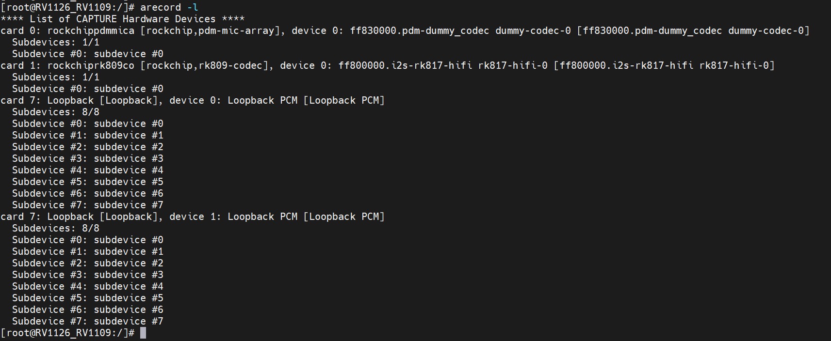
Record via digital MEMS MIC(card0).
RkLunch-stop.sh
amixer -c 1 cset numid=1 3
arecord -Dhw:0,0 -d 15 -f cd -r 44100 -c 2 -t wav test0.wav
aplay -Dhw:1,0 test0.wav
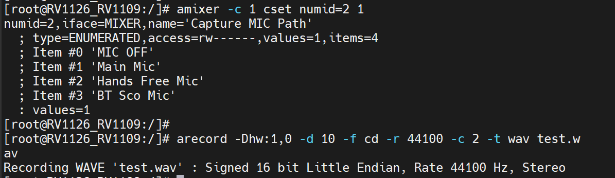
Record via differential MIC(card1).
amixer -c 1 cset numid=1 3
amixer -c 1 cset numid=2 1
arecord -Dhw:1,0 -d 15 -f cd -r 44100 -c 2 -t wav test.wav
aplay -Dhw:1,0 test.wav
6.5 WiFi
Connect the wifi antenna and power on.
ifconfig eth0 down
ifconfig
iwlist wlan0 scan
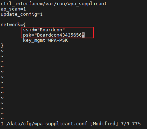
vi /data/cfg/wpa_supplicant.conf
Input your SSID and password.
rm /var/run/wpa_supplicant/wlan0
wpa_supplicant -B -i wlan0 -c /data/cfg/wpa_supplicant.conf
ping -I wlan0 www.boardcon.com
6.6 Bluetooth
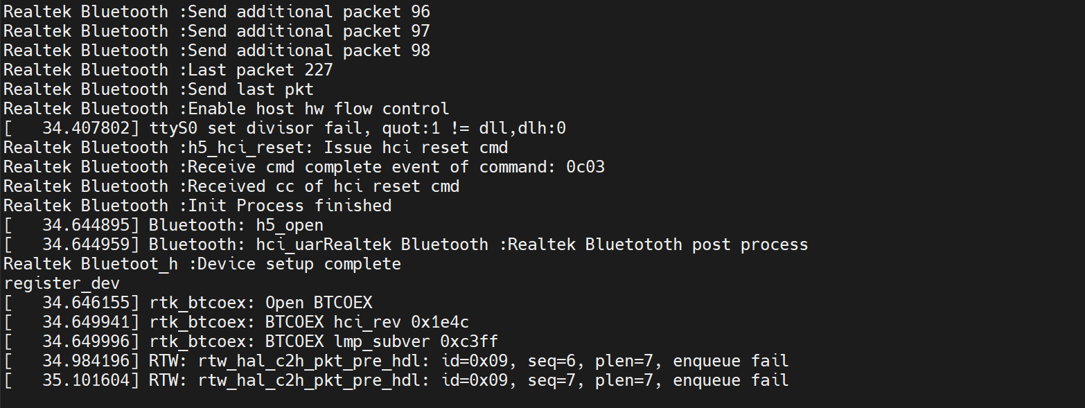
source open-bt.sh
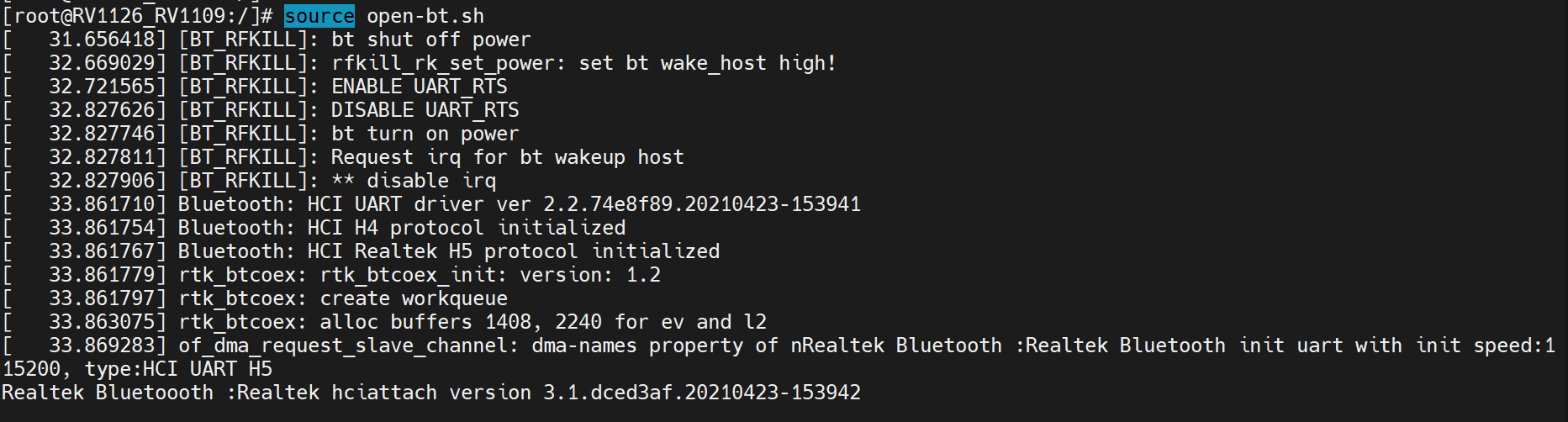
Bluetooth initialization completed.
Find the buletooth device and pair.
hciconfig hci0 piscan
hcitool scan
bluetoothctl
power on
agent on
scan on
exit
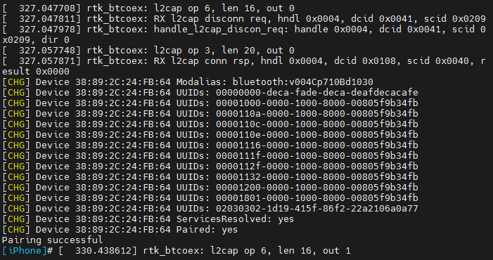
bluetoothctl
pair 38:89:2C:24:FB:64
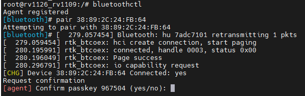
Input yes
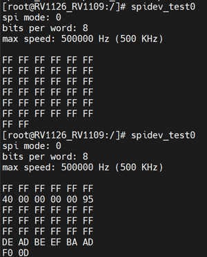
6.7 SPI
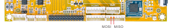
spidev_test0
Connect SPI0 MOSI and MISO(pin2&pin3) then execute command again.
spidev_test0
6.8 GPIO
Connector |
Pin |
Singal Name |
ID |
Voltage |
|---|---|---|---|---|
J5 |
2 |
GPIO2-D6 |
94 |
3.3V |
J5 |
3 |
GPIO2-D7 |
95 |
3.3V |
J18 |
2 |
GPIO3_D1 |
121 |
1.8V |
J18 |
3 |
GPIO4_A1 |
129 |
1.8V |
J36 |
2 |
GPIO2_C4 |
84 |
3.3V |
J36 |
3 |
GPIO2_C5 |
85 |
3.3V |
J36 |
4 |
GPIO2_B1 |
73 |
3.3V |
J36 |
5 |
GPIO2_B2 |
74 |
3.3V |
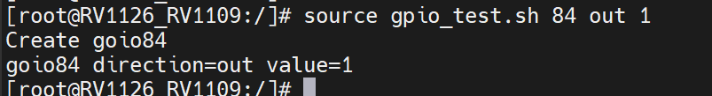
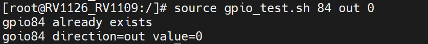
source gpio_test.sh 84 out 1 // GPIO2_C4 output high voltage
source gpio_test.sh 84 out 0 // GPIO2_C4 output low voltage
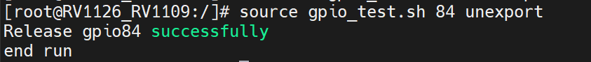
source gpio_test.sh 84 unexport // Unexport GPIO2_C4
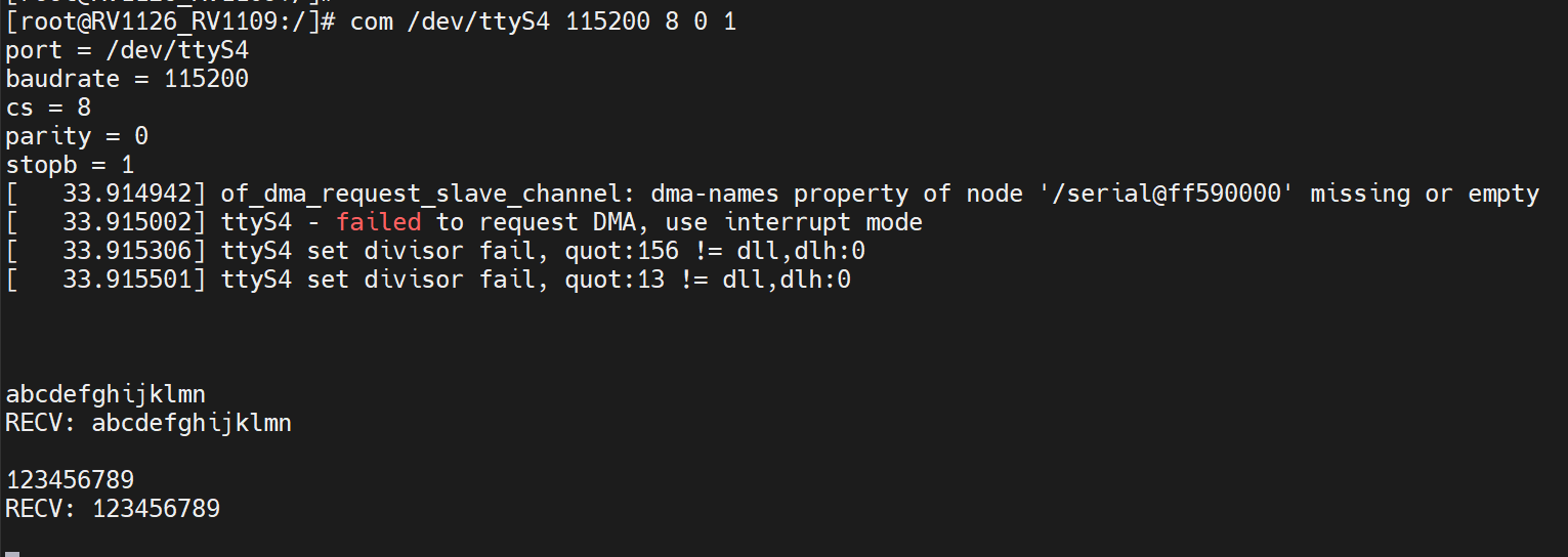
6.9 UART
connect the transmit (TX) to the receive (RX) of UART4. After execute the command, input character to test UART.
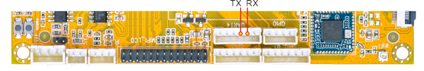
com /dev/ttyS4 115200 8 0 1
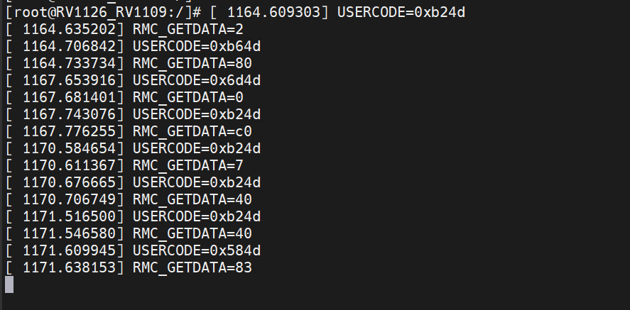
6.10 IR
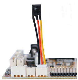
echo 1 > /sys/module/rockchip_pwm_remotectl/parameters/code_print
Operate the IR controller and view the received data after execute the command.
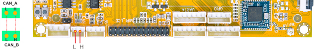
6.11 CAN
❶ Connect the CAN ports of board A and board B.
❷ Execute the following commands on the serial terminal of board A and board B.
ip link set can0 type can bitrate 500000
ip link set can0 up
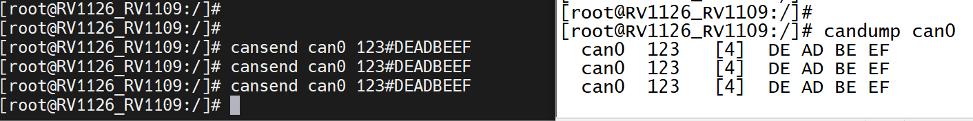
❸ Set one development board as receiver.
candump can0 //set to receiver
❹ The other board send characters as transmitter.
cansend can0 123#DEADBEEF //CAN0 send characters
6.12 RS485
This test method is only for reference.
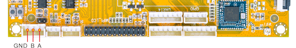
❶ Connect the RS485 ports of Board A and B with the test line.
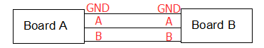
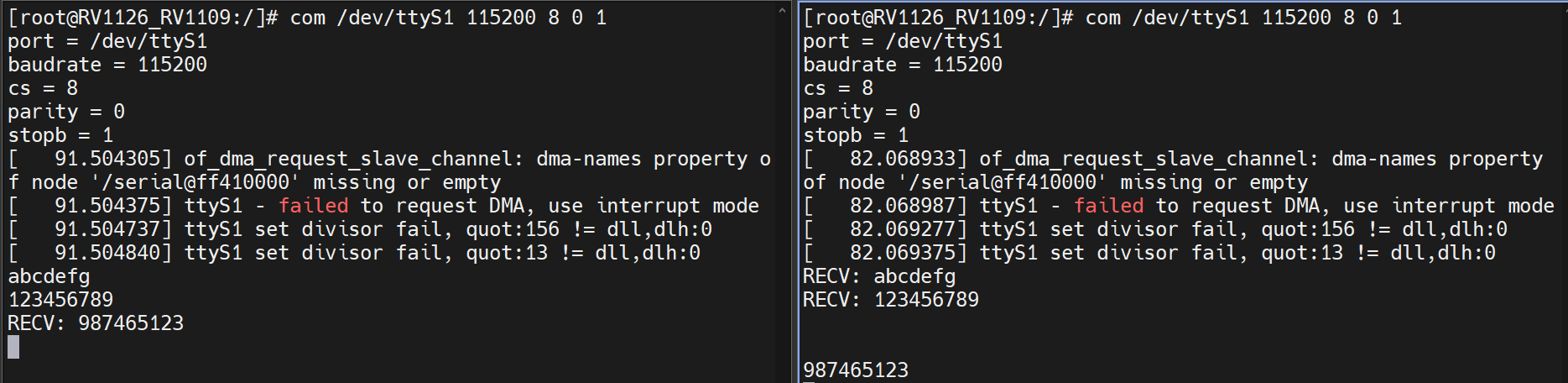
❷ Execute the command at Serial terminal.
com /dev/ttyS1 115200 8 0 1
❸ Input character to test RS485 communication.
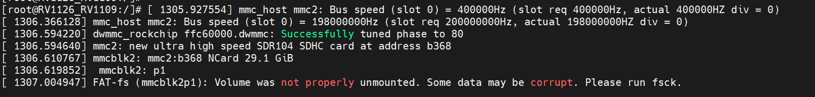
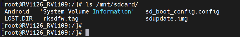
6.13 SD Card
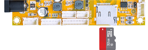
The SD card is automatically mounted. Execute the command to view SD contents.
ls /mnt/sdcard
6.14 ADC
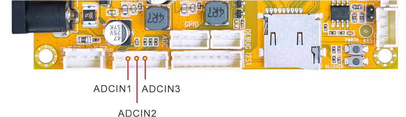
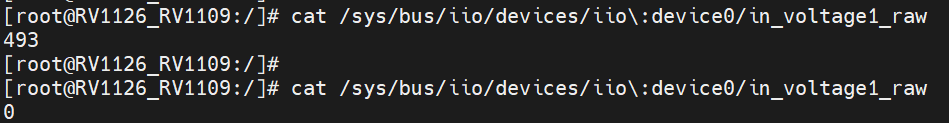
Test ADCIN1(voltage1)
cat /sys/bus/iio/devices/iio\:device0/in_voltage1_raw // View the ADC value
Connect ADCIN1 to VDDIO_18 or GND, then execute the command again.
Test ADCIN2
cat /sys/bus/iio/devices/iio\:device0/in_voltage2_raw
Test ADCIN3
cat /sys/bus/iio/devices/iio\:device0/in_voltage3_raw
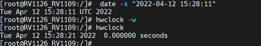
6.15 RTC
Execute the command at CRT terminal.
date -s "2022-04-12 15:28:11"     // Set system time
hwclock -w                        // Synchronize system time and RTC time
hwclock
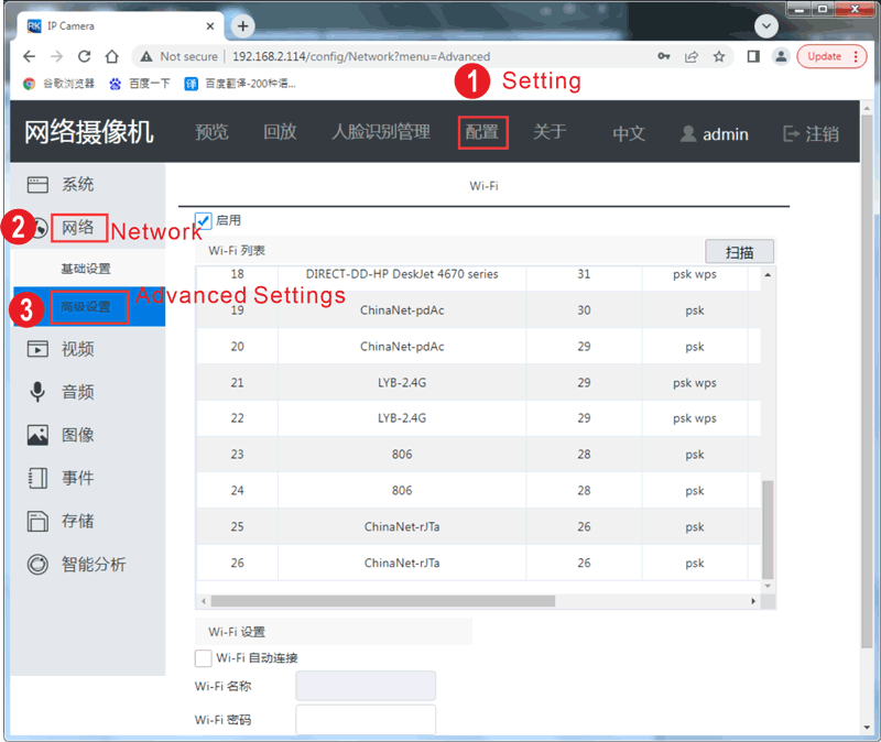
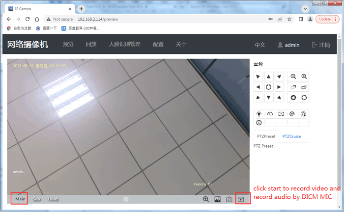
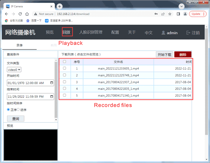
6.16 IP Camera
❶ Connect the IP camera to the EM1126 and startup. Make sure that the EM1126 and computer are in the same LAN.
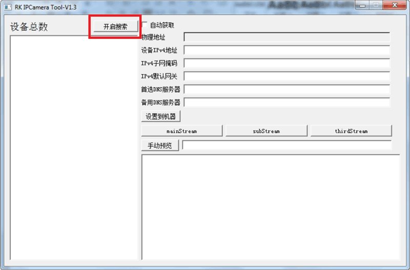
❷ Open RK IPCamera Tool.exe
❸ Click 开启搜索(Open search) to find the IP address of the IP camera.
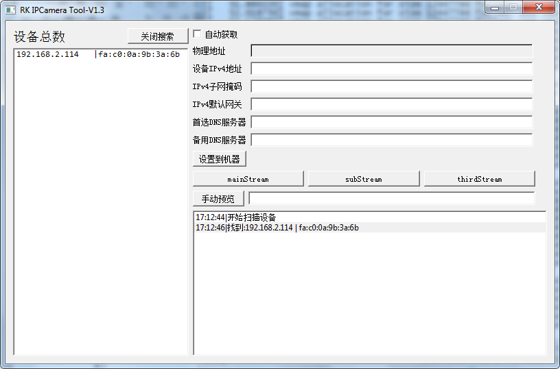
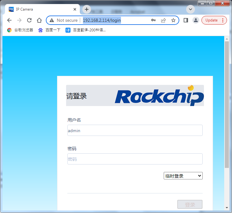
❹ Access the web interface of the IP camera using a web browser on the computer. 192.168.2.114 is the camera IP for example.
User: admin
Password: admin
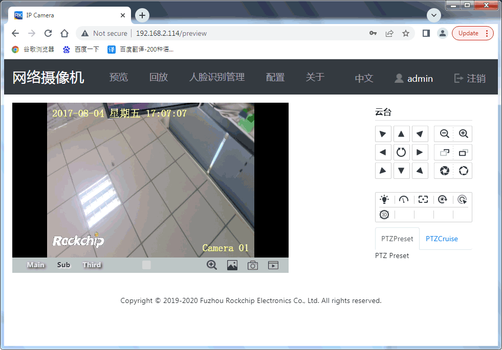
❺ Configure the network settings of the IP camera