6. Android Application
6.1 Display
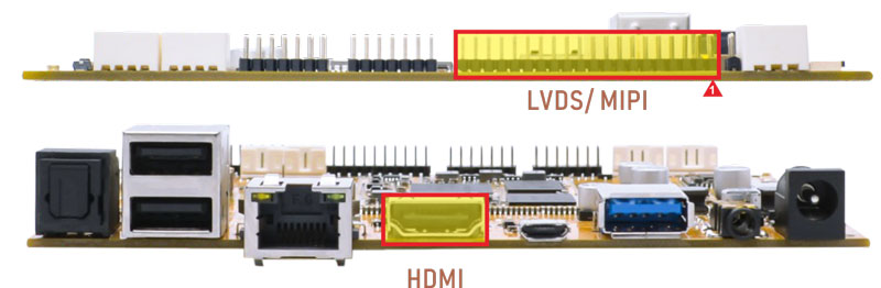
Connect the board and monitor with a HDMI cable, then start up.
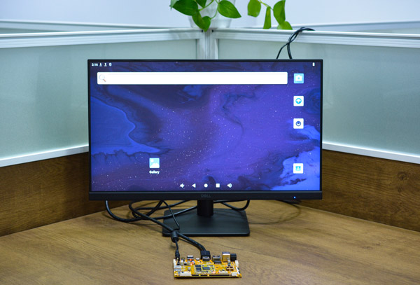
HDMI display
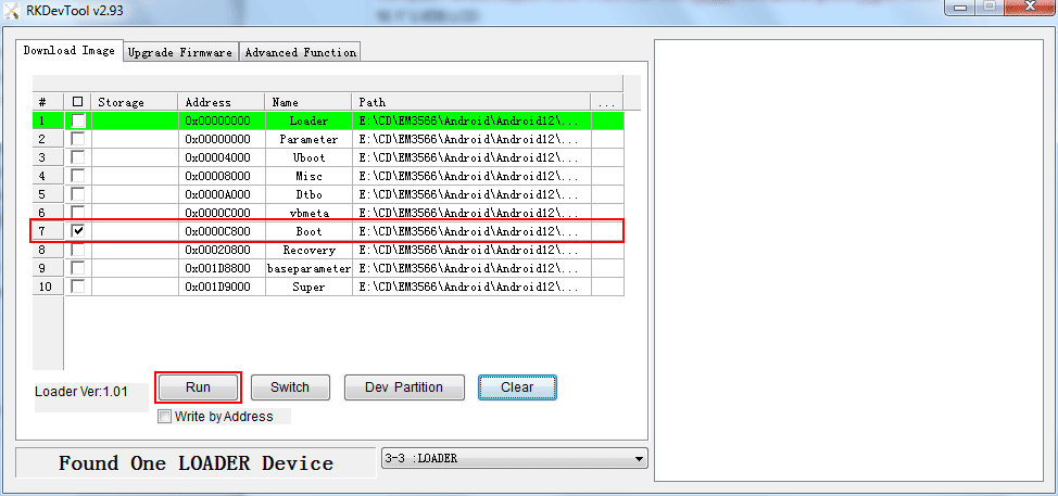
Note
The Boardcon factory default HDMI display. If change to LVDS/MIPI LCD, please reflash the corresponding
boot.img
10.1” MIPI LCD:
boot_10.1inch_mipi.img10.1” LVDS LCD:
boot_10.1inch_lvds.img7” LVDS LCD:
boot_7inch_lvds.imgHDMI:
boot_hdmi.img
1wm density 240   //10.1-inch LVDS
2wm density 180   //7-inch LVDS
6.2 SD Card
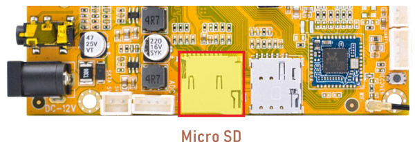
EM3566 supports SD Hot-plug. Click Explorer icon to view the mounted SD card.
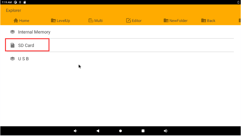
Mounted SD card
6.3 USB
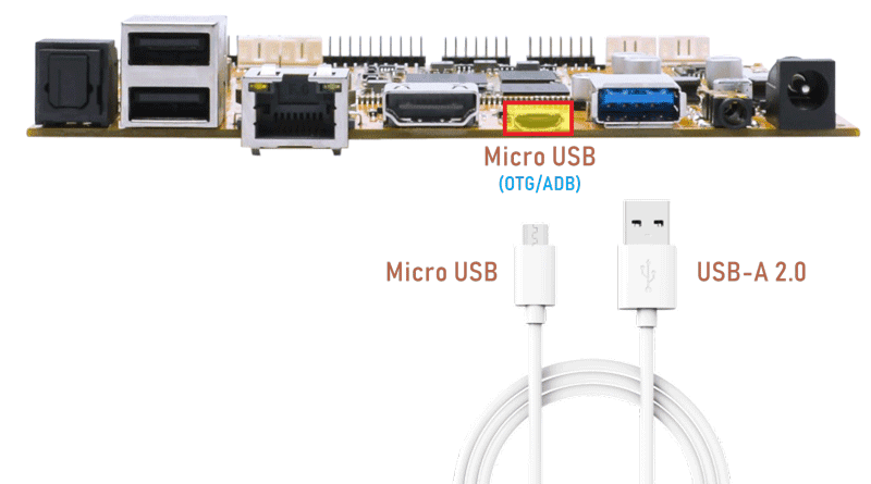
6.3.1 Micro USB
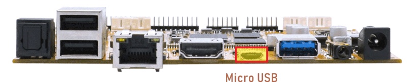
The micro USB is mainly used for firmware upgrades and ADB function.
ADB is the command-line debugging tool. It can use for system logs, uploading and downloading the files, installing the applications, etc.
❶ connect the board and PC host with Micro USB cable.
❷ install ADB driver on Windows system.
❸ press Windows + R to open the Run program. Type cmd and press Enter
❹ execute commands to enable ADB and test.
Push the file com located in PC E:\EM3566\Tool\Test\ to the board for example:
1adb root
2adb remount
3adb push E:\EM3566\Tool\Test\com /system
4adb shell
5chmod 777 /system/com    //modify com properties
6.3.2 USB Host
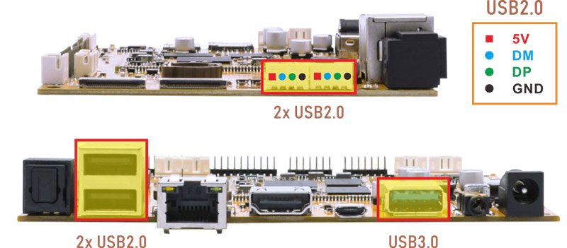
The USB2.0/3.0 Host can be used to connect USB mouse, USB keyboard, U-Disk or other USB devices.
Click Explorer icon to view the mounted U-disk.
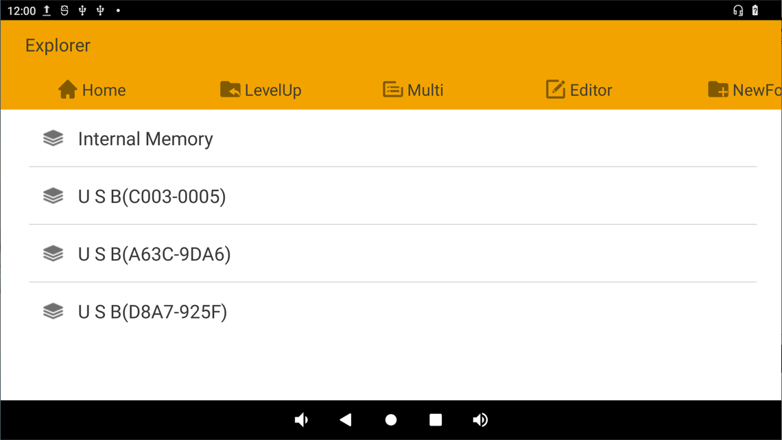
Mounted U-disk
USB3.0 Superspeed detected:
console:/ #
[   48.365328] usb 6-1: new SuperSpeed Gen 1 USB device number 3 using xhci-hcd
[   48.384073] usb 6-1: New USB device found, idVendor=3535, idProduct=6300, bcdDevice= 1.10
[   48.384147] usb 6-1: New USB device strings: Mfr=1, Product=2, SerialNumber=3
[   48.384173] usb 6-1: Product: U330
[   48.384195] usb 6-1: Manufacturer: aigo
[   48.384218] usb 6-1: SerialNumber: 52A7B285B4956ADF
[   48.388152] usb-storage 6-1:1.0: USB Mass Storage device detected
[   48.390410] scsi host0: usb-storage 6-1:1.0
[   49.416036] scsi 0:0:0:0: Direct-Access     aigo     U330             PMAP PQ: 0 ANSI: 6
[   49.418446] sd 0:0:0:0: Attached scsi generic sg0 type 0
[   49.418463] sd 0:0:0:0: [sda] 122880000 512-byte logical blocks: (62.9 GB/58.6 GiB)
[   49.419138] sd 0:0:0:0: [sda] Write Protect is off
[   49.419740] sd 0:0:0:0: [sda] Write cache: disabled, read cache: enabled, doesn't support DPO or FUA
[   49.420755] type=1400 audit(1735656221.630:81): avc: denied { create } for comm="kdevtmpfs" name="sda" scontext=u:r:kernel:s0 tcontext=u:object_r:device:s0 tclass=blk_file permissive=1
[   49.421210] type=1400 audit(1735656221.630:82): avc: denied { setattr } for comm="kdevtmpfs" name="sda" dev="devtmpfs" ino=40878 scontext=u:r:kernel:s0 tcontext=u:object_r:device:s0 tclass=blk_file permissive=1
[   49.458747]  sda: sda1
6.4 Ethernet
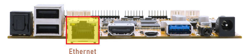
Connect the board and router with an Ethernet cable (default DHCP=Yes). User can ping URL/IP at terminal, or open the browser(Lightning) to test Network.
1ifconfig
2ping www.boardcon.com
console:/ # ifconfig
lo        Link encap:Local Loopback
          inet addr:127.0.0.1  Mask:255.0.0.0
          inet6 addr: ::1/128 Scope: Host
          UP LOOPBACK RUNNING  MTU:65536  Metric:1
          RX packets:0 errors:0 dropped:0 overruns:0 frame:0
          TX packets:0 errors:0 dropped:0 overruns:0 carrier:0
          collisions:0 txqueuelen:1000
          RX bytes:0 TX bytes:0

eth0      Link encap:Ethernet  HWaddr 52:47:13:61:97:dc  Driver rk_gmac-dwmac
          inet addr:192.168.0.253  Bcast:192.168.0.255  Mask:255.255.255.0
          inet6 addr: fe80::989e:742c:284e:702b/64 Scope: Link
          UP BROADCAST RUNNING MULTICAST  MTU:1500  Metric:1
          RX packets:48 errors:0 dropped:1 overruns:0 frame:0
          TX packets:43 errors:0 dropped:0 overruns:0 carrier:0
          collisions:0 txqueuelen:1000
          RX bytes:10446 TX bytes:4816
          Interrupt:37

dummy0    Link encap:Ethernet  HWaddr a2:f2:42:0b:f3:6a
          inet6 addr: fe80::a0f2:42ff:fe0b:f36a/64 Scope: Link
          UP BROADCAST RUNNING NOARP  MTU:1500  Metric:1
          RX packets:0 errors:0 dropped:0 overruns:0 frame:0
          TX packets:8 errors:0 dropped:0 overruns:0 carrier:0
          collisions:0 txqueuelen:1000
          RX bytes:0 TX bytes:560

console:/ # ping www.boardcon.com
PING www.boardcon.com (67.222.54.196) 56(84) bytes of data.
64 bytes from 67-222-54-196.unifiedlayer.com (67.222.54.196): icmp_seq=1 ttl=48 time=193 ms
64 bytes from 67-222-54-196.unifiedlayer.com (67.222.54.196): icmp_seq=2 ttl=48 time=188 ms
64 bytes from 67-222-54-196.unifiedlayer.com (67.222.54.196): icmp_seq=3 ttl=48 time=236 ms
64 bytes from 67-222-54-196.unifiedlayer.com (67.222.54.196): icmp_seq=4 ttl=48 time=191 ms
^C
--- www.boardcon.com ping statistics ---
4 packets transmitted, 4 received, 0% packet loss, time 4177ms
rtt min/avg/max/mdev = 188.722/202.463/236.290/19.606 ms
6.5 Audio I/O
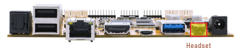
❶ plug the Headset into the 3.5mm Audio jack.
❷ open Sound Recorder
❸ click Start to start recording.
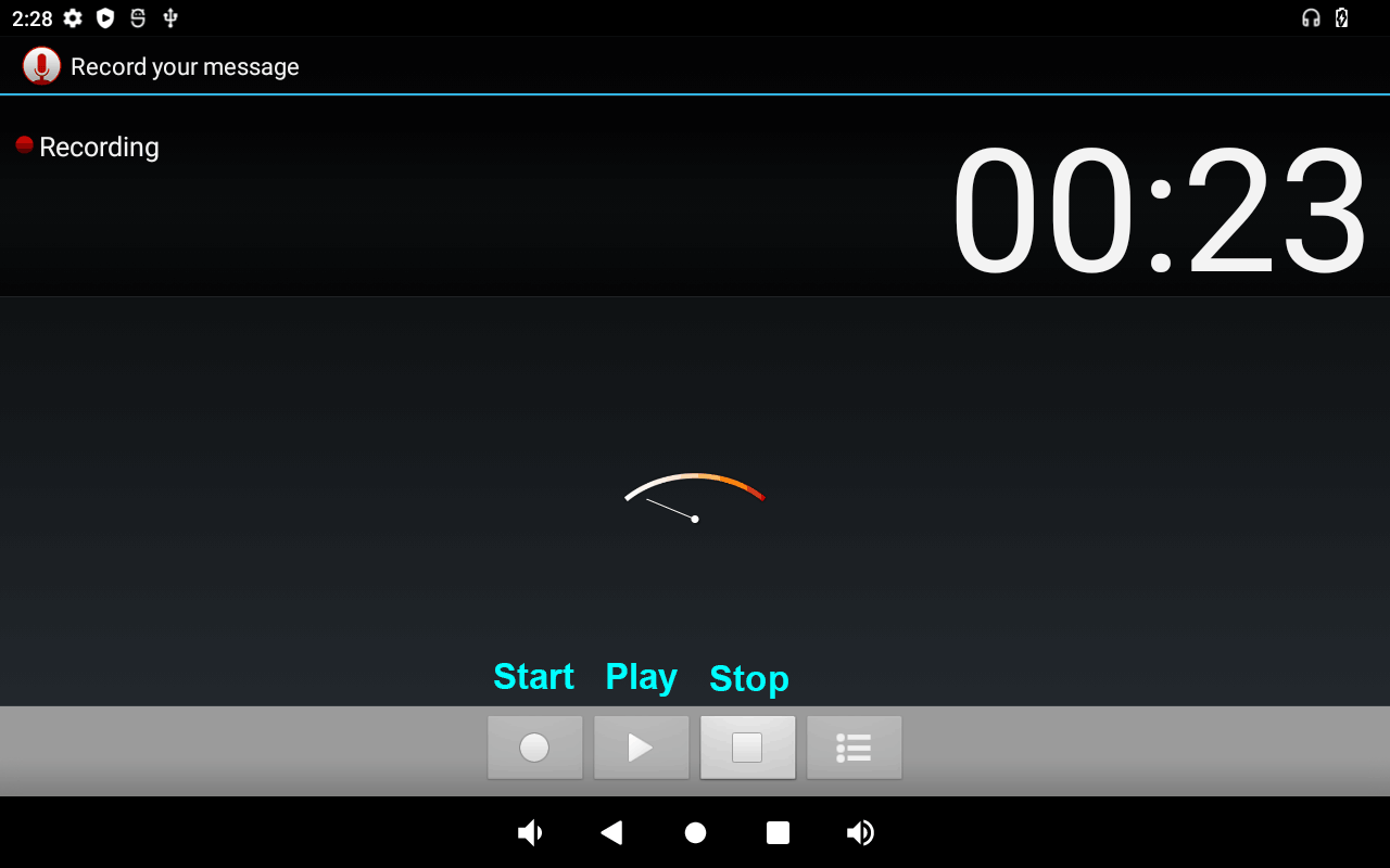
After finish recording, click Stop and Save to store file. The default storage path is Internal Memory/Recordings
Play priority: Headset output greater than HDMI out.
6.6 RTC
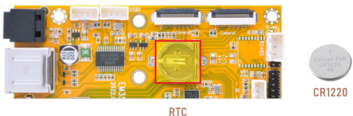
❶ insert a CR1220 battery before test. It keeps the time running when the main power is off.
❷ set date and time manually.
1date “2024-01-25 12:00:00”
2hwclock -w
3hwclock
console:/ # date "2024-01-25 12:00:00"
Thu Jan 25 00:00:00 GMT 2024
console:/ # hwclock -w
console:/ # hwclock
2024-01-25 12:00:00+0000
console:/ # hwclock
2024-01-25 12:00:11+0000
console:/ # hwclock
2024-01-25 12:00:12+0000
console:/ # hwclock
2024-01-25 12:00:15+0000
6.7 WiFi & Bluetooth
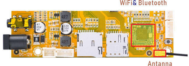
6.7.1 WiFi
❶ connect the WiFi antenna.
❷ click Settings -> Network & internet -> Wi-Fi -> turn on
❸ select the SSID from the list of available networks and enter the password.
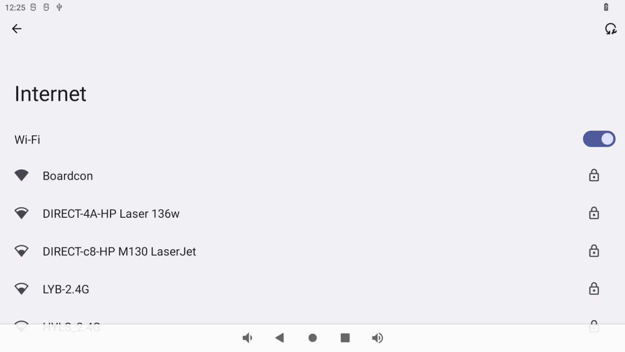
After connected, user can ping URL/IP at terminal, or open the browser to test Network.
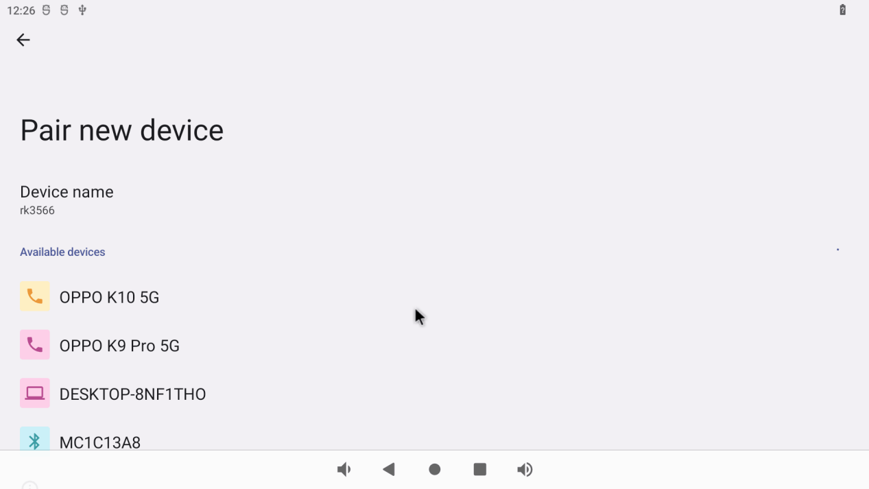
6.7.2 Bluetooth
Click Settings -> Connected devices -> Pair new device
Select the available device in the list to pair.
6.8 Camera
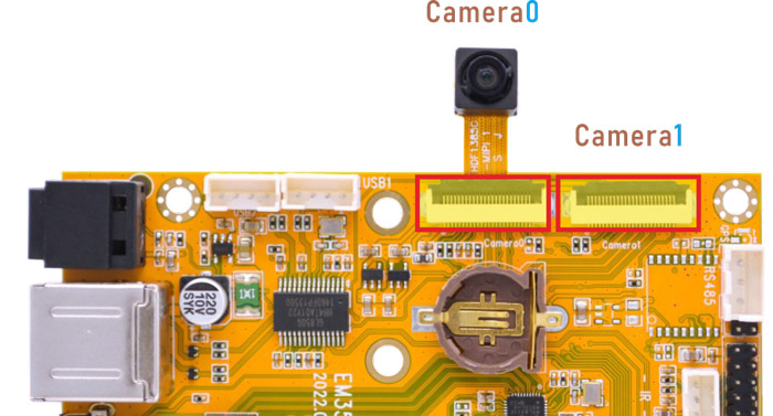
EM3566 Camera0 and camera1 share the signal I2C4, Boardcon Android 12 firmware default camera0 is enabled.
❶ connect the camera module (OV13850) to the camera0.
❷ power on.
❸ click the Camera icon to test.
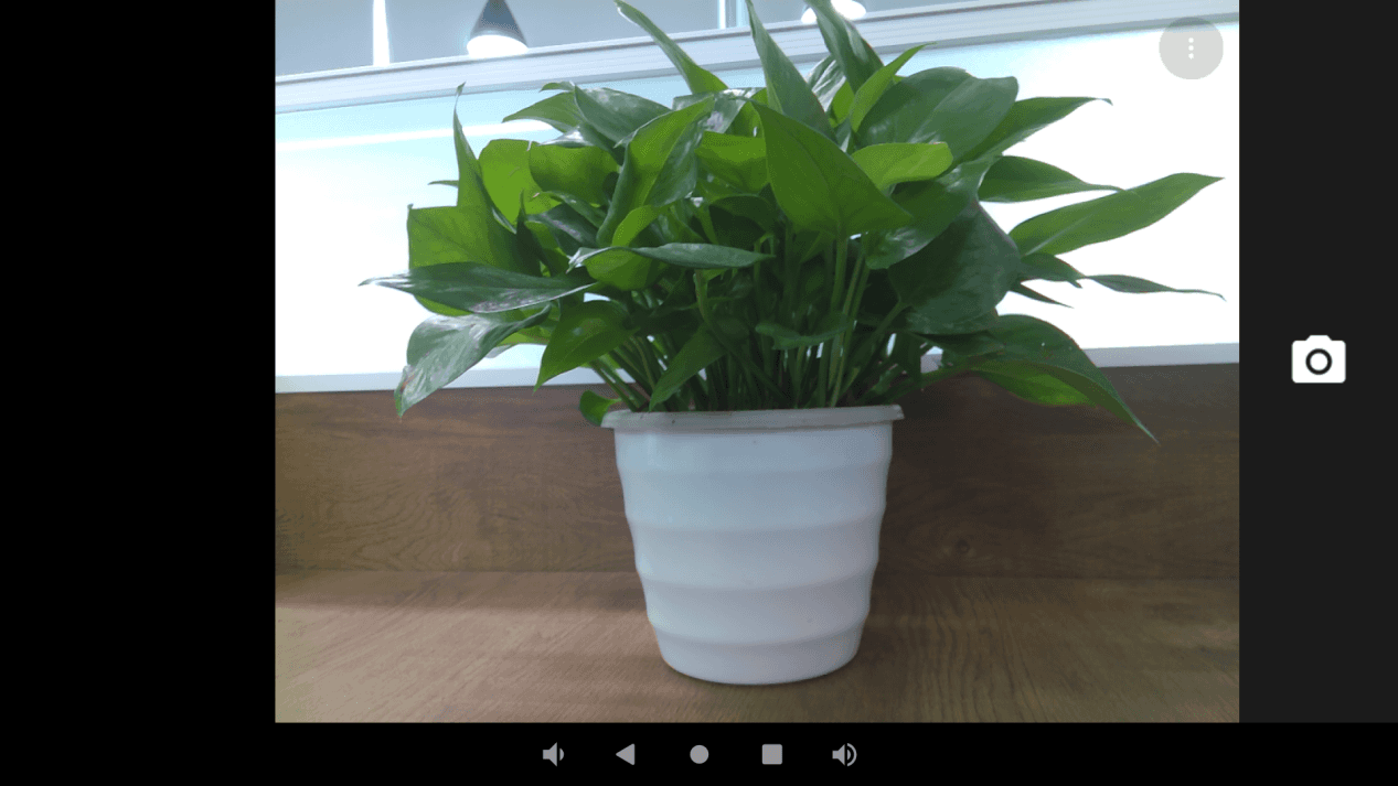
Camera preview
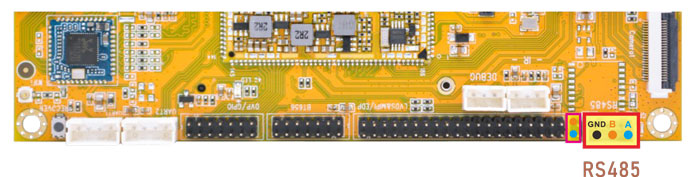
6.9 RS485
❶ push the file com to the board via ADB
❷ connect PC and board with USB-to-RS485 adapter.
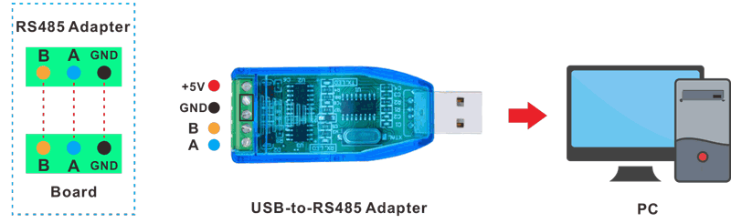
RS485 connection
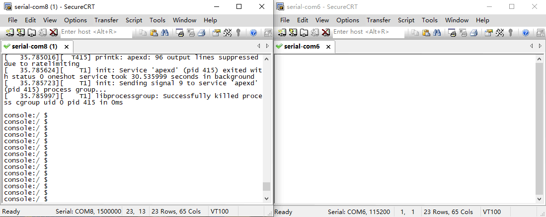
❸ open the Serial Terminal and set baud rate for the board and RS485 adapter respectively.
Baud rate: board - 1500000; RS485 adapter - 115200
❹ execute command in the terminal of the board.
1./system/com /dev/ttyS3 115200 8 0 1
❺ input character to test RS485 communication.
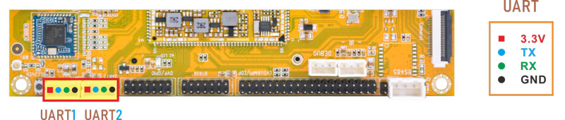
6.10 UART
The UART loopback test is for reference only.
❶ push the file com to the board via ADB
❷ connect the transmit (TX) pin to the receive (RX) pin of UART.
❸ execute the command in the terminal.
1./system/com /dev/ttyS4 115200 8 0 1 //test UART4
❹ input character to test UART.
console:/ # ./system/com /dev/ttyS4 115200 8 0 1
port = /dev/ttyS4
baudrate = 115200
cs = 8
parity = 0
stopb = 1
1234567890
RECV: 1234567890
abcdefg
RECV: abcdefg
❺ press Ctrl + C to exit UART4 testing, execute the command to test UART5.
1./system/com /dev/ttyS5 115200 8 0 1 //test UART5
console:/ # ./system/com /dev/ttyS5 115200 8 0 1
port = /dev/ttyS5
baudrate = 115200
cs = 8
parity = 0
stopb = 1
123456789999
RECV: 123456789999
abcdefghijk
RECV: abcdefghijk
6.11 M.2 SSD
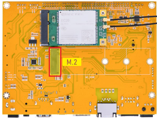
EM3566 only supports ext4 format. Format SSD to ext4 file system on Ubuntu system.
❶ view the SSD device name.
1ls /dev/block
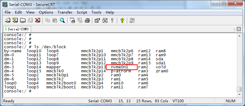
❷ format SSD on Ubuntu system.
1mke2fs -t ext4 /dev/block/nvme0n1
❸ mount SSD
1mkdir /data/ssd
2mount -t ext4 /dev/block/nvme0n1 /data/ssd
3ls /data/ssd
console:/ # mkdir /data/ssd
console:/ # mount -t ext4 /dev/block/nvme0n1 /data/ssd
[  183.670186] EXT4-fs (nvme0n1): recovery complete
[  183.670352] EXT4-fs (nvme0n1): mounted filesystem with ordered data mode. opts: (null)
console:/ # ls /data/ssd
2.wav lost+found test2 yang.mp3
console:/ #
If the SSD is auto-mounted, execute the command to test:
1ls /run/media/nvme0n1
6.12 IR
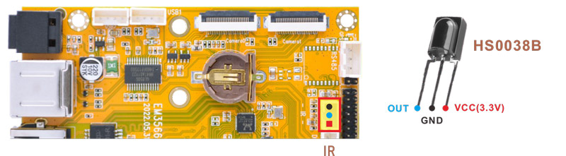
❶ connect IR receiver to the IR port.
❷ turn on IR debugging log.
1echo 1 > /sys/module/rockchip_pwm_remotectl/parameters/code_print
❸ press the Infrared controller, you can view the received datas on the terminal.
console:/ # echo 1 > /sys/module/rockchip_pwm_remotectl/parameters/code_print
console:/ # [ 1093.906505] USERCODE=0xfe01
[ 1093.933574] RMC_GETDATA=bf
[ 1094.655478] USERCODE=0xfe01
[ 1094.682612] RMC_GETDATA=ea
[ 1095.434245] USERCODE=0xfe01
[ 1095.461283] RMC_GETDATA=b8
[ 1096.472055] USERCODE=0xfe01
[ 1096.499126] RMC_GETDATA=b9
6.13 ADC
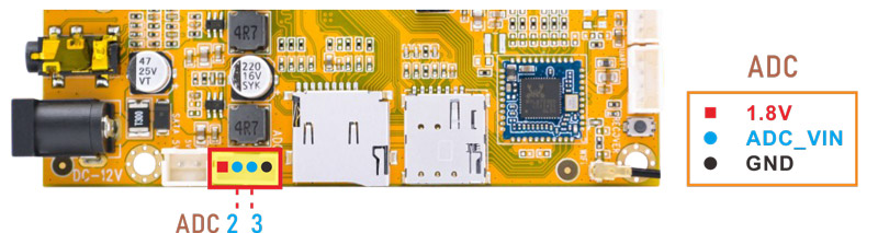
Execute the command to view the SARADC_VIN value when it is in the following states:
floating
connect to GND
connect to VDDIO_18(1.8V)
1cat /sys/devices/platform/fe720000.saradc/iio:device0/in_voltage2_raw
console:/ # cat /sys/devices/platform/fe720000.saradc/iio:device0/in_voltage2_raw
811
console:/ # cat /sys/devices/platform/fe720000.saradc/iio:device0/in_voltage2_raw
9
console:/ # cat /sys/devices/platform/fe720000.saradc/iio:device0/in_voltage2_raw
1023
1cat /sys/devices/platform/fe720000.saradc/iio:device0/in_voltage3_raw
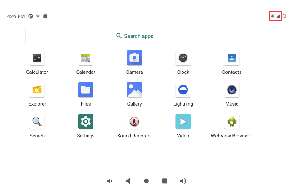
6.14 4G
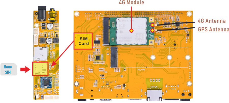
❶ insert 4G module to mPCIe slot (4G model: EC20).
❷ connect antenna and insert Nano SIM card.
❸ power on. The default connection is 4G network.
Open the browser(Lightning) or ping URL/IP at terminal to test Network.