6. Android Application
6.1 Display
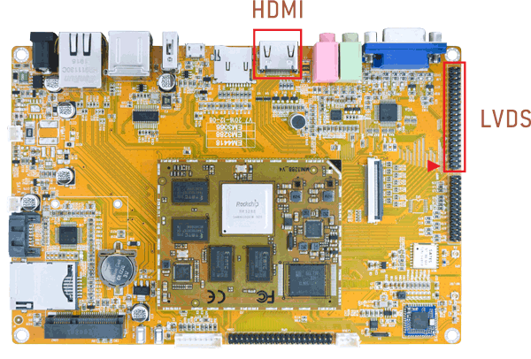
Connect the board and monitor, then start up. EM3288 supports Dual-screen display (HDMI/LVDS).
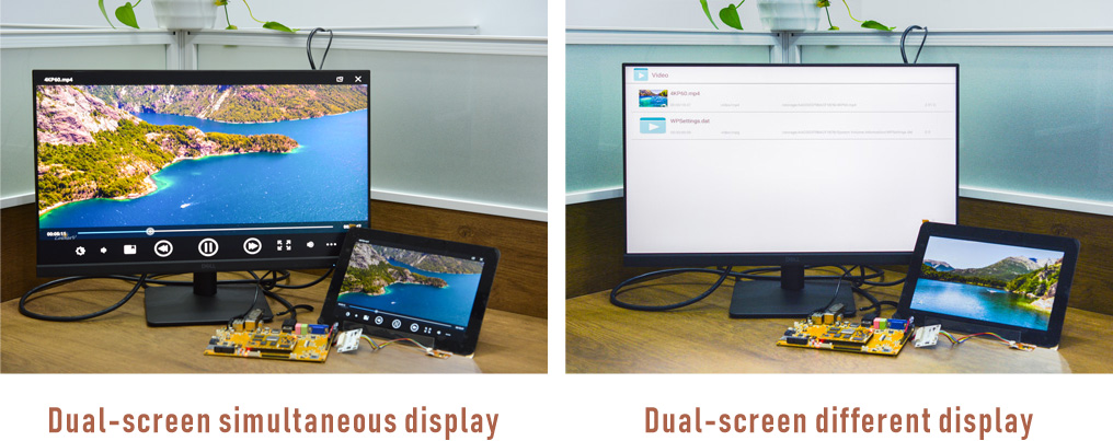
6.1.1 Dual-screen different display
Settings -> Display -> HDMI -> Turn On, check dual screen and Vice screen rotation
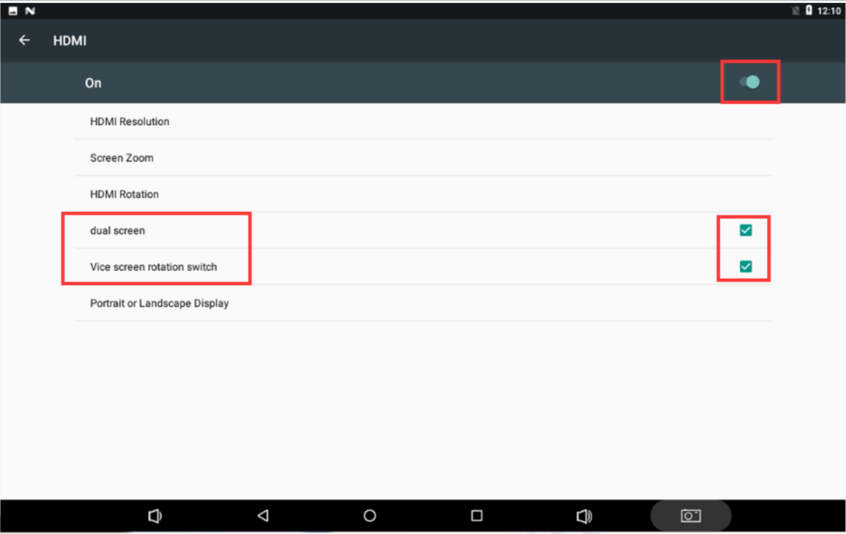
Press and hold volume + and volume simultaneously and hold for 2 seconds.

The same operation can exit the different display mode.
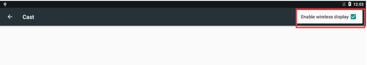
6.1.2 Miracast
Miracast is a wireless display standard designed for mirroring a smartphone, tablet, or PC’s screen to a television without requiring any physical HDMI cables.
Miracast using WiFi protocol, it must be connected to the same WiFi.
Settings -> Display -> Cast -> Check Enable wireless display
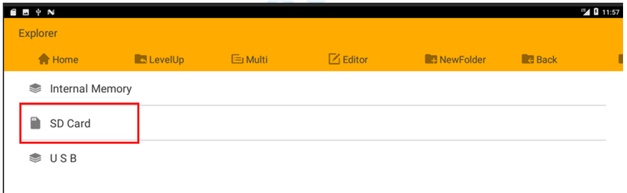
6.2 SD Card
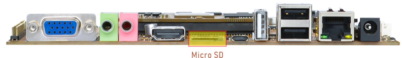
EM3288 supports SD Hot-plug.
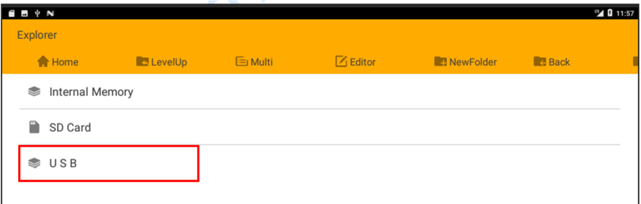
6.3 USB Host
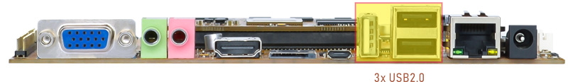
The USB2.0 Host can be used to connect USB mouse, USB keyboard, U-Disk or other USB devices. Support Hot-plug.
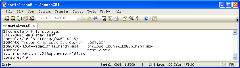
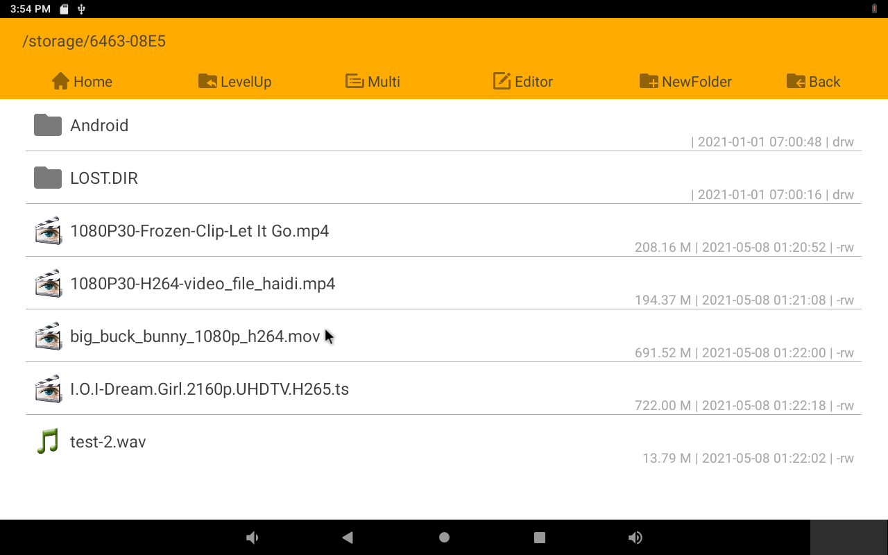
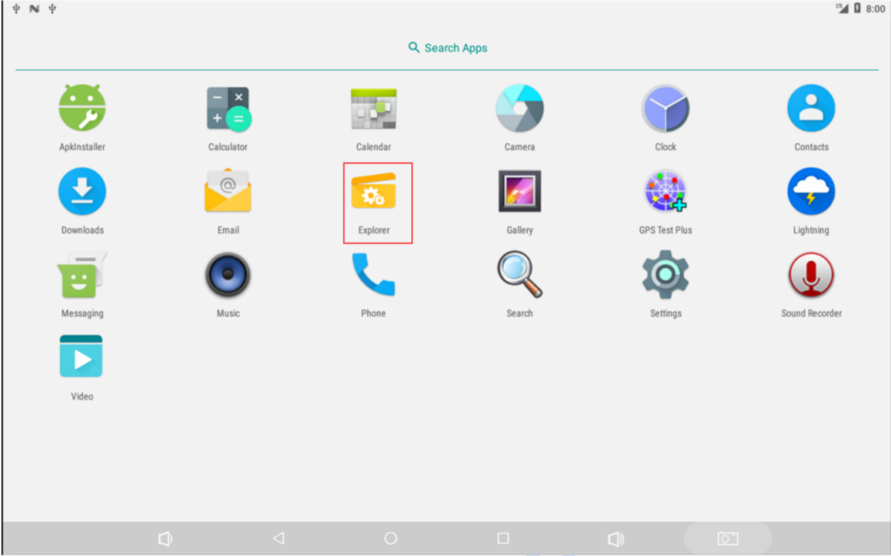
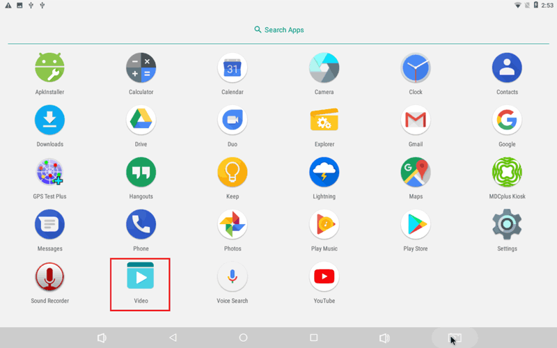
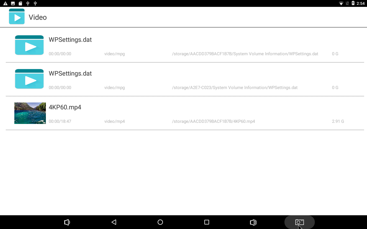
6.4 Video&Audio Player
Copy video file to SD_card/U-disk then insert it to the board. Click Video icon and select multimedia file to play.
6.5 Ethernet
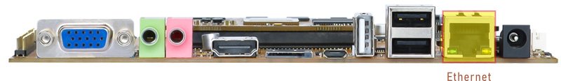
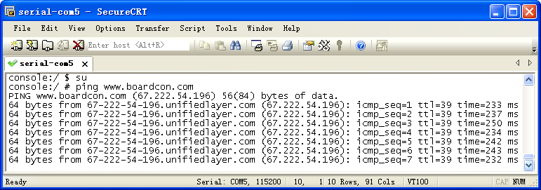
Connect the board and router with an Ethernet cable (default DHCP=Yes). User can ping URL/IP at terminal, or open the browser to test Network.
su
ping www.boardcon.com
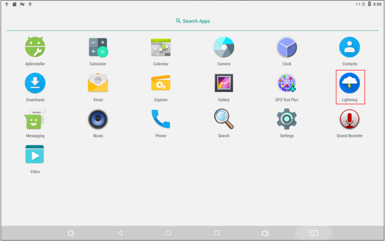
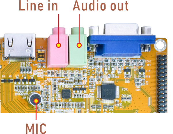
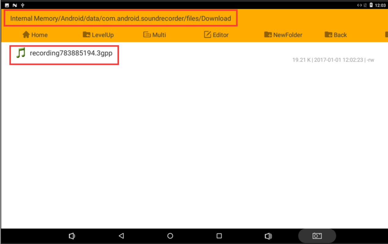
6.6 Record
EM3288 supports recording via line-in(headset) or differential MIC. Default MIC recording. It will switch to the Line_in recording automatically if inserted the headset.
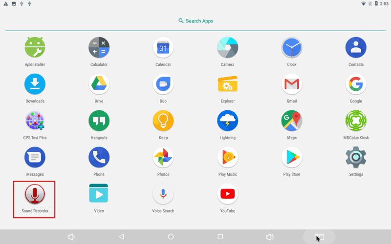
Open the APP Sound Recorder in Android.
Click Start button to start recording.
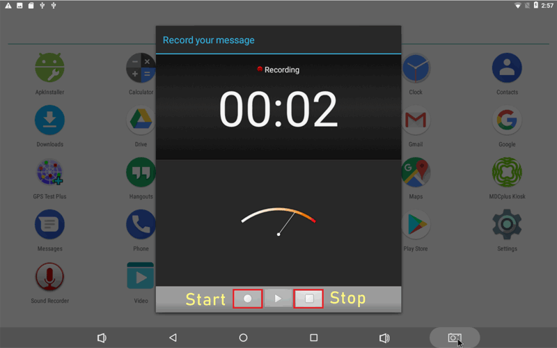
After finish recording, click Stop and Save to store file.
The default storage path is Internal Memory/Android/data/com.android.soundrecorder/files/Download
Audio output priority: Headphone > HDMI
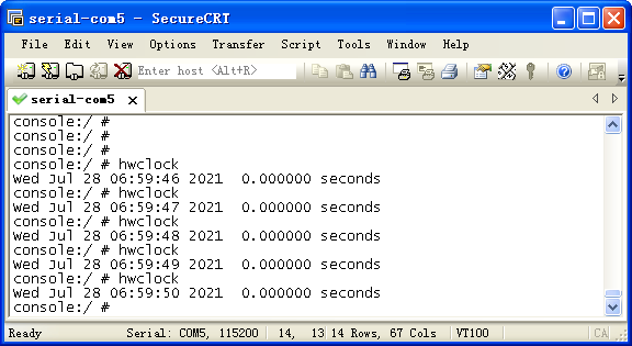
6.7 RTC
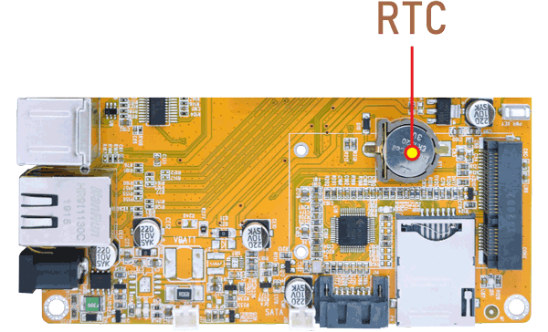
Execute the command hwclock at CRT terminal to query hardware clock
busybox hwclock
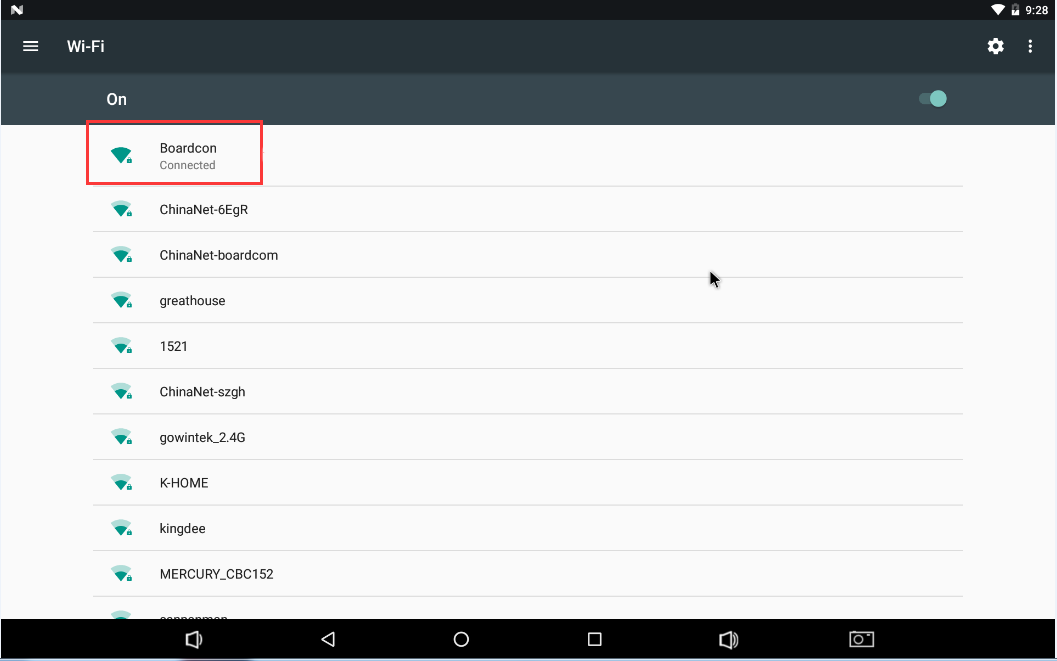
6.8 WiFi
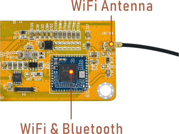
Connect the WiFi antenna, then click Settings -> Network&internet -> Wi-Fi -> turn on, select the SSID from the list of available networks and enter the password.
After connected, user can ping URL/IP at terminal, or open the browser to test Network.
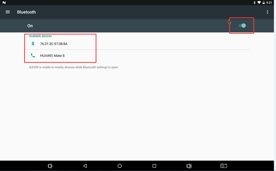
6.9 Bluetooth
Click Settings -> Bluetooth -> turn on
Select the available device in the list to pair.
6.10 4G
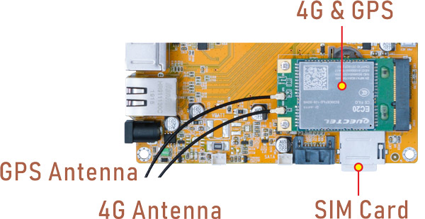
Step 1, Insert 4G module to PCIe slot (4G model: EC20/EC25).
Step 2, Connect antenna and insert SIM card.
Step 3, Power on. The default network connection is 4G network.
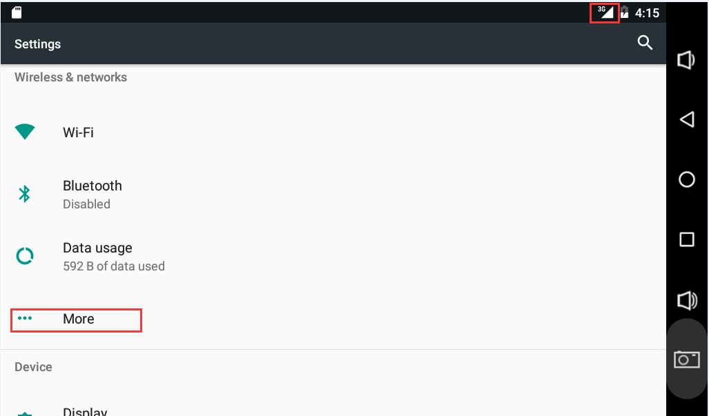
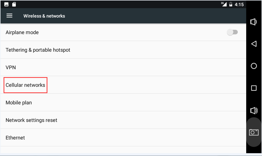
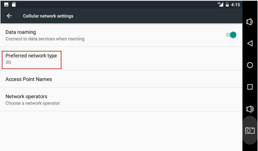
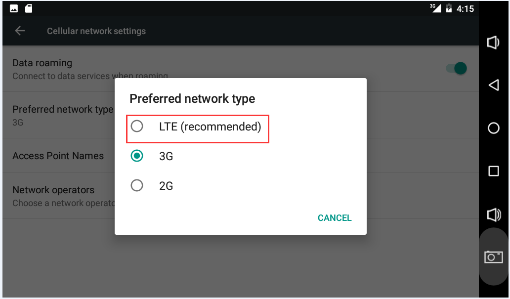
4G network settings
Settings -> Wireless&networks -> More -> Cellular networks -> Preferred network type -> LTE

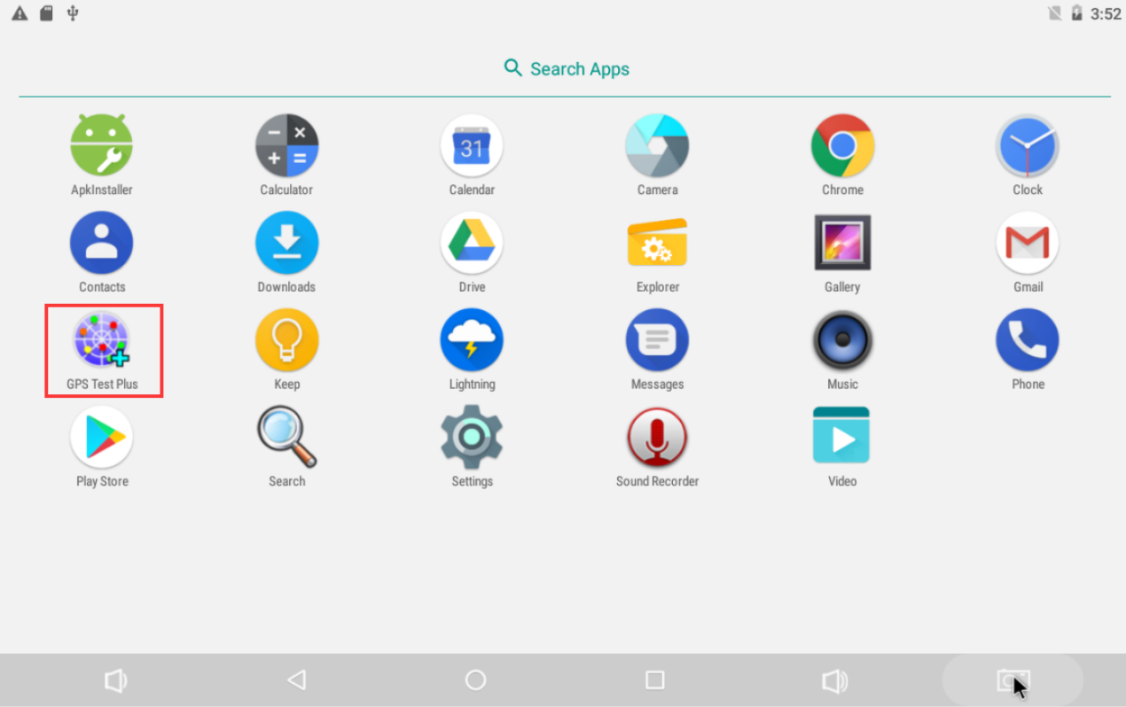
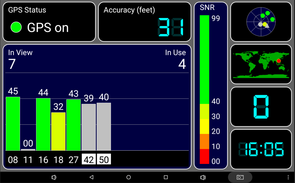
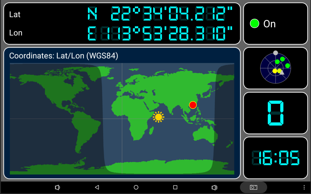
6.11 GPS
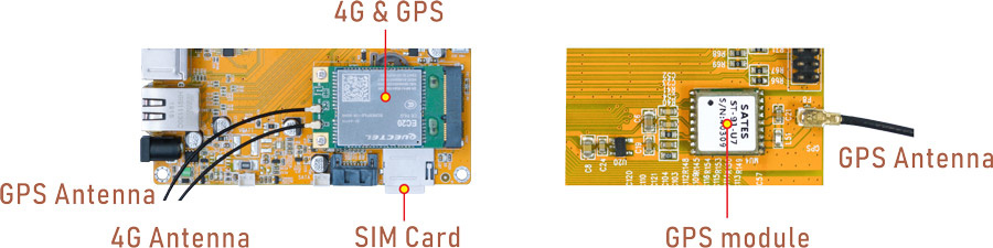
EM3288 4G module combines high-speed wireless connectivity with embedded multi-constellation high-sensitivity GPS+GLONASS receiver for positioning.
In addition, the development board also supports a standalone GPS module(Model: ST-91-U7).
Connect GPS antenna, then power on and install the APP /Tools/GPS_test1.2.4.apk
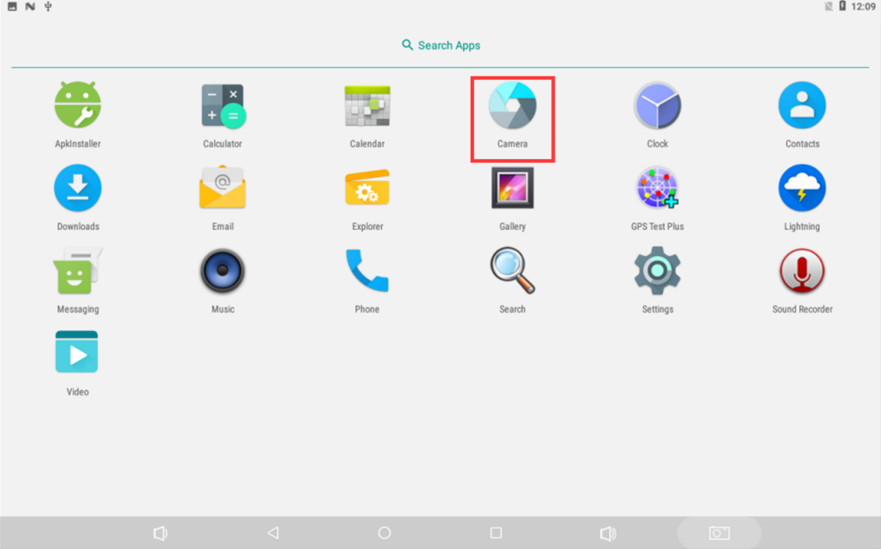
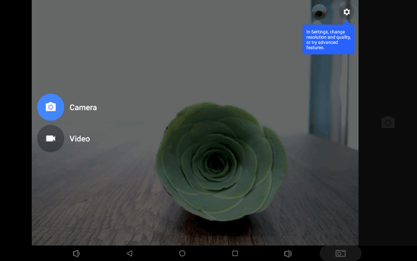
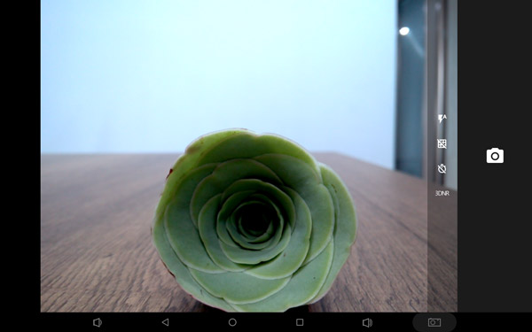
6.12 Camera
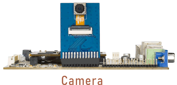
Connect the camera module (OV13850) to the development board before power on, then click the camera APP to test.
6.11 UART
The UART loopback test is for reference only.
Step 1, push the file com to the test board via ADB
adb root
adb remount
adb push \xx\com /system  //\xx\ is the absolute path to store com
adb shell
chmod 777 /system/com    //Modify com properties
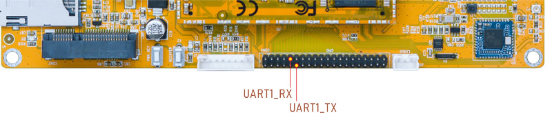
Step 2, connect the transmit (TX) pin to the receive (RX) pin of UART1
Step 3, after executes the command, input character to test UART
./system/com /dev/ttyS1 115200 8 0 1 //Test UART1
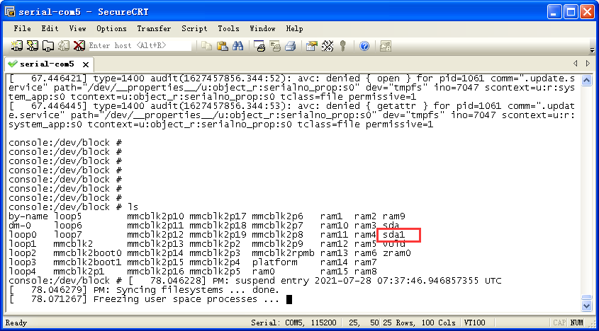
6.12 SATA
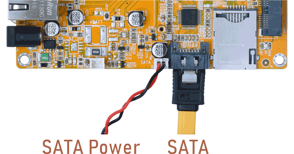
Connect the SATA and SATA-power to the development board before power on,then the SATA will auto mount.
Since SATA requires a relatively high current, the SATA power supply on the EM3288 may not provide sufficient current, leading to instability. Therefore, it is advisable to provide SATA power externally.