3. IPC Application
In the IPC rockit version, the rkipc service starts automatically after system boot. To avoid conflicts during function tests, stop the rkipc service before testing other functions.
1RkLunch-stop.sh
1RkLunch.sh
3.1 Serial Terminal
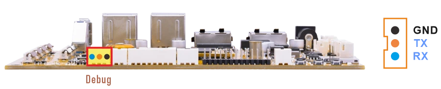
❶ Connect the USB-to-serial module to the PC and connect the other end to the Debug UART interface on the board.
❷ Open a serial terminal tool on the PC, select the corresponding serial port, and set the baud rate to 1500000.
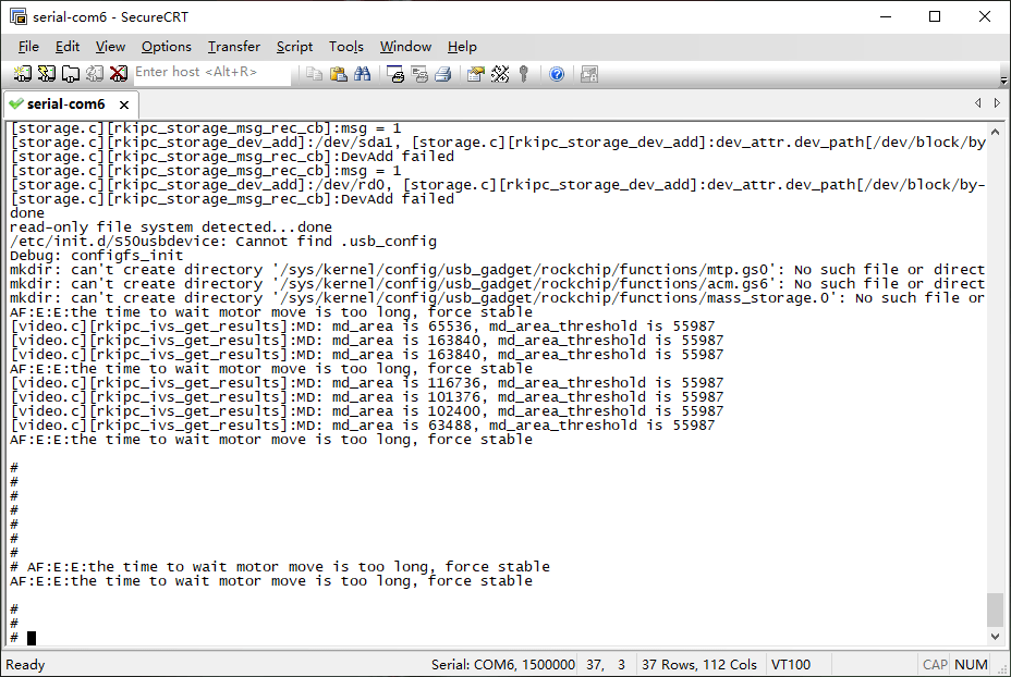
❸ Power on the board and check whether the boot log is displayed in the serial terminal.
3.2 Display
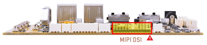
The default MIPI display resolution of the SBC1126B is 800×1280@60 Hz.
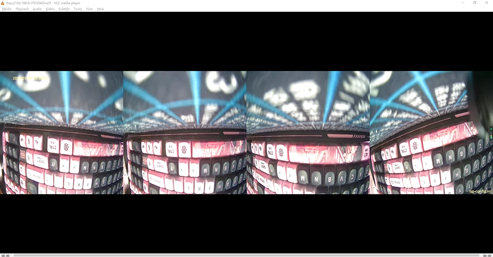
In the IPC version, the system does not display the desktop by default after boot. After flashing the corresponding firmware image and connecting the supported cameras before power-on, the system automatically starts the camera preview. The display output shows the stitched preview image from the connected camera channels. If no camera is connected or the connected camera does not match the flashed firmware image, the display remains black after boot.
3.3 USB
3.3.1 USB3.0 DRD
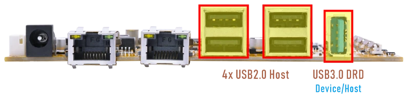
The USB3.0 DRD supports both Host and Device roles, with Device as the default configuration for image flashing/upgrading. It can be switched to host mode by command, after which it supports peripherals such as mouse, keyboards, and USB flash drives.
1echo host > /sys/kernel/debug/usb/21500000.usb/mode
In USB host mode, when a USB flash drive is connected, it is mounted automatically. The current USB connection speed can be checked in the kernel log.
When the device operates in USB2.0 mode, the log usually shows high-speed.
When the device operates in USB3.0 mode, the log usually shows SuperSpeed.
1echo device > /sys/kernel/debug/usb/21500000.usb/mode
3.3.2 USB2.0 Host
The USB2.0 Host can connect peripherals such as mouse, keyboards, and flash drives.
After a USB flash drive is connected, it will be mounted automatically. Check the mounted path.
1df -h
# df -h
Filesystem                Size      Used Available Use% Mounted on
/dev/root                49.5M     49.5M         0 100% /
devtmpfs                 60.4M         0     60.4M   0% /dev
tmpfs                   966.9M         0    966.9M   0% /dev/shm
tmpfs                   966.9M      8.0K    966.9M   0% /tmp
tmpfs                   966.9M    384.0K    966.5M   0% /run
/dev/block/by-name/oem
                        237.9M     58.1M    164.3M  26% /oem
/dev/block/by-name/userdata
                          5.8G      9.3M      5.7G   0% /userdata
/dev/sda1                32.0G      5.4G     26.6G  17% /tmp/sda1
3.4 Audio
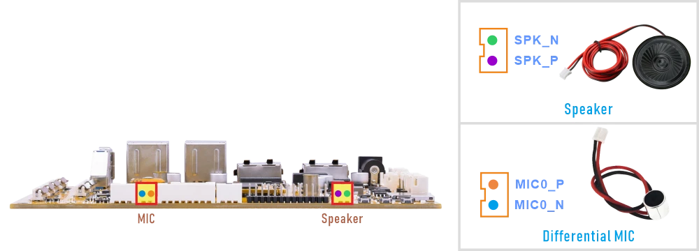
3.4.1 Audio Output
❶ Connect the Speaker to the connector (2-pin/2.0mm pitch)
❷ Set the DAC digital volume.
1rk_mpi_amix_test -C 0 --control 'DAC Digital Volume' --value '250,250'
❸ Play the audio file.
Execute command according to the actual audio file path, eg. /tmp/sda1/video/music/2.wav
1rk_mpi_ao_test -i /tmp/sda1/video/music/2.wav --input_ch 2 --input_rate 44100 --device_rate 44100 --device_ch 2 --sound_card_name hw:0,0
3.4.2 Audio Input
❶ Stop the rkipc service.
1RkLunch-stop.sh
# RkLunch-stop.sh
Stop Application ...
[rkipc.c][sig_proc]:received signo 15
killall: udhcpc: no process killed
  349 root     2827m S<   rkipc -a /oem/usr/share/iqfiles
rkipc active
[server.c][rkipc_server_deinit]:rkipc_server_deinit failed
[osd.c][osd_time_server]:exit
[video.c][rkipc_osd_bmp_destroy]:RK_MPI_RGN_Destroy [2] failed with 0xa0038005
[video.c][rkipc_osd_bmp_destroy]:RK_MPI_RGN_Destroy [3] failed with 0xa0038005
[video.c][rkipc_osd_cover_destroy]:RK_MPI_RGN_Destroy [4] failed with 0xa0038005
[video.c][rkipc_osd_cover_destroy]:RK_MPI_RGN_Destroy [11] failed with 0xa0038005
❷ Select MIC as the recording input source.
1rk_mpi_amix_test -C 0 --control 'SAI2 Receive PATH0 Source Select' --value 'From SDI0'
# rk_mpi_amix_test -C 0 --control 'SAI2 Receive PATH0 Source Select' --value  'F
rom SDI0'
cmd parse result:
sound control id      : 0
control name          : SAI2 Receive PATH0 Source Select
control value         : From SDI0
list controls         : 0
list contents         : 0
❸ Set the audio codec digital gain.
1rk_mpi_amix_test -C 0 --control 'ACodec Digital Gain Volume' --value '100'
# rk_mpi_amix_test -C 0 --control 'ACodec Digital Gain Volume' --value '100'
cmd parse result:
sound control id      : 0
control name          : ACodec Digital Gain Volume
control value         : 100
list controls         : 0
list contents         : 0
❹ Record audio from MIC.
1rk_mpi_ai_test --device_rate 44100 --device_ch 2 --out_rate 44100 --out_ch 2 -o /userdata --sound_card_name hw:0,0
# rk_mpi_ai_test --device_rate 44100 --device_ch 2 --out_rate 44100 --out_ch 2 -
o /userdata --sound_card_name hw:0,0
cmd parse result:
input  file name      : (null)
output file name      : /userdata
loop count            : 1
channel number        : 1
open sound rate       : 44100
record data rate      : 44100
sound card channel    : 2
output channel        : 2
bit_width             : 16
frame_number          : 4
frame_length          : 1024
sound card name       : hw:0,0
device id             : 0
set volume curve      : 0
set volume            : 100
set mute              : 0
set track_mode        : 0
get volume            : 0
get mute              : 0
get track_mode        : 0
data read enable      : 0
aed enable            : 0
bcd enable            : 0
buz enable            : 0
vqe gap duration (ms) : 16
vqe enable            : 0
get vqe result        : 0
bcd NN model path     : (null)
vqe config file       : (null)
dump algo pcm data    : 0
dev queue len         : 0
sed queue len         : 0
fd get enable         : 1
rockit_load start
v4l2_tx probe successv4l2_rx_probe success
rockit_load end
rockit log path (null), log_size = 0
log_file = (nil)
(null)           12:01:15-450 {log_level_init    :209}

 please use echo name=level > /tmp/rt_log_level set log level
        name: all cmpi mb sys vdec venc rgn vpss vgs tde avs wbc vo vi ai ao aenc adec
        log_level: 0 1 2 3 4 5 6
❺ Play the recorded audio through the speaker.
1rk_mpi_ao_test -i /data/cap_out.pcm --input_ch 2 --input_rate 44100 --device_rate 44100 --device_ch 2 --sound_card_name hw:0,0
# rk_mpi_ao_test -i /data/cap_out.pcm --input_ch 2 --input_rate 44100 --device_r
ate 44100 --device_ch 2 --sound_card_name hw:0,0
cmd parse result:
input  file name      : /data/cap_out.pcm
output file name      : (null)
loop count            : 1
channel number        : 1
open sound rate       : 44100
open sound channel    : 2
input stream rate     : 44100
input channel         : 2
bit_width             : 16
period_count          : 4
period_size           : 4096
sound card name       : hw:0,0
device id             : 0
set volume curve      : 0
set volume            : 100
set mute              : 0
set track_mode        : 0
get volume            : 0
get mute              : 0
get track_mode        : 0
query stat            : 0
pause and resume chn  : 0
save file             : 0
query save file stat  : 0
clear buf             : 0
get attribute         : 0
clear attribute       : 0
set loopback mode     : 0
vqe enable            : 0
rockit_load start
v4l2_tx probe successv4l2_rx_probe success
rockit_load end
rockit log path (null), log_size = 0
log_file = (nil)
(null)           12:02:41-705 {log_level_init    :209}

 please use echo name=level > /tmp/rt_log_level set log level
        name: all cmpi mb sys vdec venc rgn vpss vgs tde avs wbc vo vi ai ao aenc adec
        log_level: 0 1 2 3 4 5 6
3.5 Ethernet
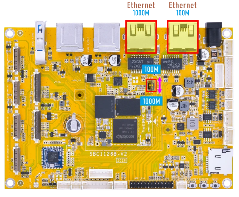
The 100M Ethernet and 1000M Ethernet interfaces on the SBC1126B are multiplexed and cannot be used at the same time. When switching between them, the corresponding firmware image must be updated in software, and the hardware selection must also be changed using the DIP switch on the development board.
DTS Configuration Switching Instructions File path sysdrv\source\kernel\arch\arm64\boot\dts\rockchip\boardcon-sbc1126b.dtsi
//#include "boardcon-sbc1126b-gephy.dtsi" //1000M
#include "boardcon-sbc1126b-fephy.dtsi"   //100M
#include "boardcon-sbc1126b-gephy.dtsi"    //1000M
//#include "boardcon-sbc1126b-fephy.dtsi"  //100M
3.5.1 100M Ethernet
❶ Connect the network cable to the 100M Ethernet port, and set the DIP switch to the 100M position.
According to the log, it can be seen that the 100M Ethernet recognition is successful.
# dmesg | grep -Ei "link|100Mbps"
[    0.268284] NET: Registered PF_NETLINK/PF_ROUTE protocol family
[    0.712381] mpp_rkvdec2 22140100.rkvdec: link mode probe finish
[    0.719821] can: netlink gateway - max_hops=1
[    1.368230] rk_gmac-dwmac 21c70000.ethernet eth0: configuring for phy/rmii link mode
[    2.726968] dw-mipi-dsi-rockchip 22120000.dsi: [drm:dw_mipi_dsi_bridge_atomic_enable] final DSI-Link bandwidth: 468 x 4 Mbps
[   12.969534] rk_gmac-dwmac 21c70000.ethernet eth0: configuring for phy/rmii link mode
[  162.477091] rk_gmac-dwmac 21c70000.ethernet eth0: Link is Up - 100Mbps/Full - flow control rx/tx
[  162.477120] IPv6: ADDRCONF(NETDEV_CHANGE): eth0: link becomes ready
❷ View the status of the network interface.
1ifconfig eth0
# ifconfig eth0
eth0      Link encap:Ethernet  HWaddr 0A:E7:14:87:42:44
          inet addr:192.168.0.221  Bcast:192.168.0.255  Mask:255.255.255.0
          inet6 addr: fe80::8e7:14ff:fe87:4244/64 Scope:Link
          UP BROADCAST RUNNING MULTICAST  MTU:1500  Metric:1
          RX packets:759 errors:0 dropped:92 overruns:0 frame:0
          TX packets:18 errors:0 dropped:0 overruns:0 carrier:0
          collisions:0 txqueuelen:1000
          RX bytes:63001 (61.5 KiB)  TX bytes:2428 (2.3 KiB)
          Interrupt:91
❸ Test network connectivity.
1ping -I eth0 www.armdesigner.com
# ping -I eth0 www.armdesigner.com
PING www.armdesigner.com (13.249.126.87): 56 data bytes
64 bytes from 13.249.126.87: seq=0 ttl=246 time=169.120 ms
64 bytes from 13.249.126.87: seq=1 ttl=246 time=169.190 ms
64 bytes from 13.249.126.87: seq=2 ttl=246 time=168.847 ms
64 bytes from 13.249.126.87: seq=3 ttl=246 time=170.724 ms
64 bytes from 13.249.126.87: seq=4 ttl=246 time=169.255 ms
64 bytes from 13.249.126.87: seq=5 ttl=246 time=169.033 ms
^C
--- www.armdesigner.com ping statistics ---
6 packets transmitted, 6 packets received, 0% packet loss
round-trip min/avg/max = 168.847/169.361/170.724 ms
3.5.2 1000M Ethernet
❶ Connect the network cable to the 1000M Ethernet port, and set the DIP switch to the 1000M position.
According to the log, it can be seen that the 1000M Ethernet recognition is successful.
# dmesg | grep -Ei "link|1Gbps"
[    0.266194] NET: Registered PF_NETLINK/PF_ROUTE protocol family
[    0.806565] mpp_rkvdec2 22140100.rkvdec: link mode probe finish
[    0.814165] can: netlink gateway - max_hops=1
[    1.376796] rk_gmac-dwmac 21c70000.ethernet eth0: configuring for phy/rgmii link mode
[    2.772943] dw-mipi-dsi-rockchip 22120000.dsi: [drm:dw_mipi_dsi_bridge_atomic_enable] final DSI-Link bandwidth: 468 x 4 Mbps
[   13.856116] rk_gmac-dwmac 21c70000.ethernet eth0: configuring for phy/rgmii link mode
[  158.253401] rk_gmac-dwmac 21c70000.ethernet eth0: Link is Up - 1Gbps/Full - flow control rx/tx
[  158.253500] IPv6: ADDRCONF(NETDEV_CHANGE): eth0: link becomes ready
❷ View the status of the network interface.
1ifconfig eth0
❸ Test network connectivity.
1ping -I eth0 www.armdesigner.com
3.6 SD Card
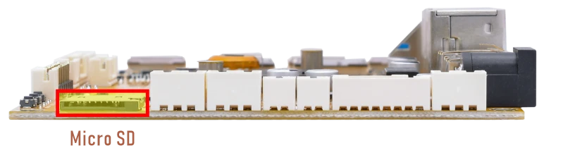
After the micro SD card is inserted and recognized successfully, it will be mounted automatically. Run the following command to check the mount path of the SD card.
1df -h
Filesystem                Size      Used Available Use% Mounted on
/dev/root                47.5M     47.5M         0 100% /
devtmpfs                 60.4M         0     60.4M   0% /dev
tmpfs                   966.9M         0    966.9M   0% /dev/shm
tmpfs                   966.9M     16.0K    966.9M   0% /tmp
tmpfs                   966.9M    664.0K    966.3M   0% /run
/dev/block/by-name/oem
                        237.9M     55.3M    167.2M  25% /oem
/dev/block/by-name/userdata
                          5.8G     49.5M      5.6G   1% /userdata
/dev/sda1                58.0G     37.5G     20.4G  65% /tmp/sda1
/dev/mmcblk1p1           30.0G      4.5G     25.4G  15% /mnt/sdcard
3.7 WiFi & Bluetooth
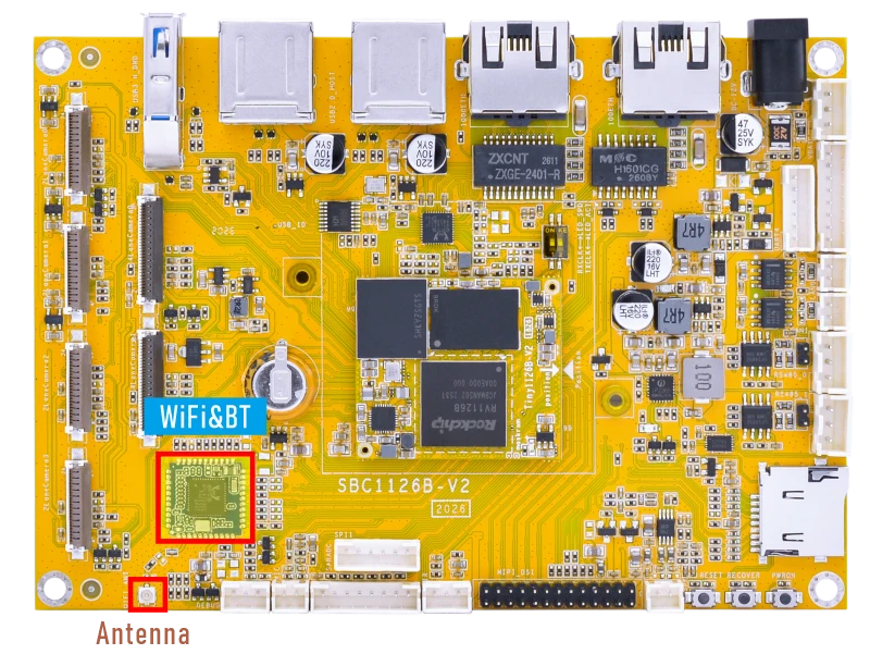
3.7.1 WiFi
❶ Connect the WiFi antenna.
❷ Check the Wi-Fi device information.
1ifconfig wlan0
# ifconfig wlan0
wlan0     Link encap:Ethernet  HWaddr 6C:D5:52:A2:3A:35
          UP BROADCAST MULTICAST  MTU:1500  Metric:1
          RX packets:0 errors:0 dropped:0 overruns:0 frame:0
          TX packets:0 errors:0 dropped:0 overruns:0 carrier:0
          collisions:0 txqueuelen:1000
          RX bytes:0 (0.0 B)  TX bytes:0 (0.0 B)
❸ Scan for available WiFi hotspots.
1wpa_cli -i wlan0 scan
2wpa_cli -i wlan0 scan_results
❹ Connect hotspot.
1rkwifi_server connect SSID PSK //'SSID': user SSID, 'PSK': password
After connecting, check the network status and test Wi-Fi connectivity.
1ifconfig wlan0
2ping -I wlan0 www.armdesigner.com
3.7.2 Bluetooth
By default, the device is configured to operate as a Bluetooth speaker. The following steps describe how to pair with and connect to a device:
❶ Start the BlueALSA A2DP sink service.
1bluealsa -p a2dp-sink &
# bluealsa -p a2dp-sink &
# bluealsa: W: Couldn't create storage directory: No such file or directory
bluealsa: E: Couldn't acquire D-Bus name. Please check D-Bus configuration. Requested name: org.bluealsa

[1]+  Done(1)                    bluealsa -p a2dp-sink
❷ Enter the Bluetooth control tool.
1bluetoothctl
# bluetoothctl
Waiting to connect to bluetoothd...Waiting to connect to bluetoothd...[bluetooth]#                                    hci0 new_settings: powered bondable ssp br/edr le secure-conn
[bluetooth]# [bluetooth]#                         Agent registered
[bluetooth]# [bluetooth]#                         [CHG] Controller 6C:D5:52:A2:3A:36 Pairable: yes
[bluetooth]# [bluetooth]#
❸ Enable Bluetooth and set it to discoverable mode.
Execute the following commands in bluetoothctl:
1power on
2discoverable on
[bluetooth]# [bluetooth]# power on
[bluetooth]# [bluetooth]#                         Changing power on succeeded
[bluetooth]# [bluetooth]# discoverable on
[bluetooth]# [bluetooth]#                         hci0 new_settings: powered connectable bondable ssp br/edr le secure-conn
[bluetooth]# [bluetooth]#                         hci0 new_settings: powered connectable discoverable bondable ssp br/edr le secure-conn
[bluetooth]# [bluetooth]#                         Changing discoverable on succeeded
[bluetooth]# [bluetooth]#                         [CHG] Controller 6C:D5:52:A2:3A:36 Discoverable: yes
[bluetooth]# [bluetooth]#
After this step, the Bluetooth device can be discovered by the phone.
❹ Pair and connect the Bluetooth device.
On the phone, find the Bluetooth device named BlueZ 5.77 in the Bluetooth device list, then tap it to pair and connect.
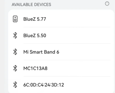
If a pairing confirmation message appears, confirm it on both the phone and the board.
[bluetooth]# [bluetooth]#                         hci0 new_settings: powered connectable bondable ssp br/edr le secure-conn
[bluetooth]# [bluetooth]#                         hci0 new_settings: powered connectable discoverable bondable ssp br/edr le secure-conn
[bluetooth]# [bluetooth]#                         Changing discoverable on succeeded
[bluetooth]# [bluetooth]#                         [CHG] Controller 6C:D5:52:A2:3A:36 Discoverable: yes
[bluetooth]# [bluetooth]#                         hci0 A8:35:12:9A:EB:4D type BR/EDR connected eir_len 11
[bluetooth]# [bluetooth]#                         [NEW] Device A8:35:12:9A:EB:4D liuy
[bluetooth]# [bluetooth]# [liuy]#                         Request confirmation
[liuy]# [liuy]# [agent] Confirm passkey 303999 (yes/no): yes
[liuy]# [liuy]#                    hci0 new_link_key A8:35:12:9A:EB:4D type 0x05 pin_len 0 store_hint 1
[liuy]# [liuy]#                    hci0 device_flags_changed: A8:35:12:9A:EB:4D (BR/EDR)
[liuy]# [liuy]#                         supp: 0x00000000  curr: 0x00000000
[liuy]# [liuy]#                    [CHG] Device A8:35:12:9A:EB:4D ServicesResolved: yes
[liuy]# [liuy]#                    [CHG] Device A8:35:12:9A:EB:4D Paired: yes
[liuy]# [liuy]#                    Authorize service
[liuy]# [liuy]# [agent] Authorize service 0000110d-0000-1000-8000-00805f9b34fb (yes/no): yes
                 [CHG] Device A8:35:12:9A:EB:4D UUIDs: 8ce255c0-200a-11e0-ac64-0800200c9a66
[liuy]# [liuy]#
Check the log output to confirm the MAC address. In this example, the MAC address of the mobile phone is A8:35:12:9A:EB:4D.
❺ Exit bluetoothctl.
1exit
❻ Start Bluetooth audio playback.
1bluealsa-aplay A8:35:12:9A:EB:4D &
[liuy]# exit
# bluealsa-aplay A8:35:12:9A:EB:4D &
# bluealsa-aplay: W: Couldn't open ALSA mixer: Mixer element not found
#
After the Bluetooth connection is established, play audio on the phone. The audio should be output from the board.
3.8 IR

❶ Connect the IR receiver.
❷ Enable IR debug logs.
1echo 1 > /sys/module/rockchip_pwm_remotectl/parameters/code_print
❸ Press remote button, key value printed to log.
# echo 1 > /sys/module/rockchip_pwm_remotectl/parameters/code_print
# dmesg | grep -Ei "USERCODE|RMC_GETDATA"
[   46.215271] USERCODE=0x1818
[   46.242508] RMC_GETDATA=e6
[   46.629794] USERCODE=0x1818
[   46.656951] RMC_GETDATA=9a
[   47.177519] USERCODE=0x1818
[   47.204731] RMC_GETDATA=9b
[   48.986199] USERCODE=0x1818
[   49.013275] RMC_GETDATA=99
[   49.326217] USERCODE=0x1818
[   49.353353] RMC_GETDATA=99
[   49.667350] USERCODE=0x1818
[   49.694497] RMC_GETDATA=9a
[   49.961815] USERCODE=0x1818
[   49.988972] RMC_GETDATA=98
[   51.210911] USERCODE=0x1818
3.9 RS485
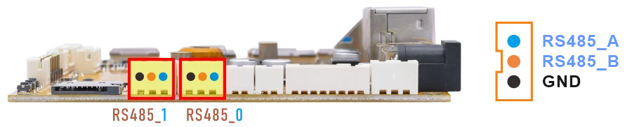
❶ Connect PC and board with USB-to-RS485 adapter.
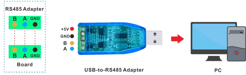
RS485 connection
❷ Open two serial terminal windows. Set the debug serial port baud rate to 1500000, and set the RS485 serial port baud rate to 115200.
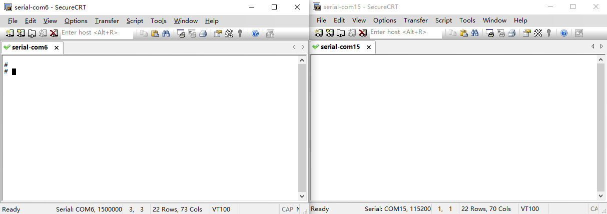
❸ Execute command on the terminal serial port of board to test RS485_0.
1com /dev/ttyS5 115200 8 0 1
❹ Input character to test RS485 communication.
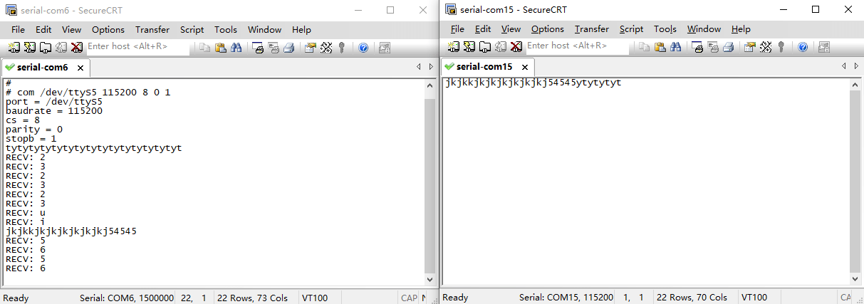
❺ Press Ctrl + C to exit RS485_0 testing.
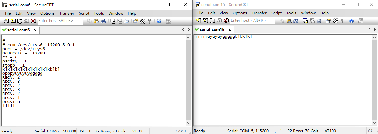
❻ Test RS485_1.
1com /dev/ttyS6 115200 8 0 1
3.10 UART
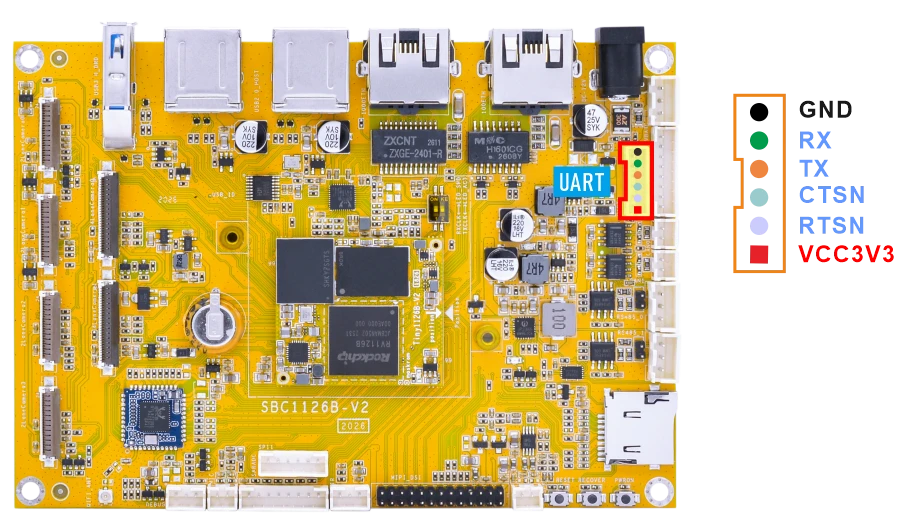
❶ Connect RX and TX of UART.
❷ Execute command and input character to test.
1com /dev/ttyS4 115200 8 0 1
# com /dev/ttyS4 115200 8 0 1
port = /dev/ttyS4
baudrate = 115200
cs = 8
parity = 0
stopb = 1
1212121212121
RECV: 1212121212121
opopopopopo
RECV: opopopopopo
yuyuyuyuyu
RECV: yuyuyuyuyu
kklklklkl
3.11 CAN
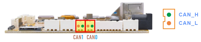
❶ Connect PC and board with USB-to-CAN adapter.
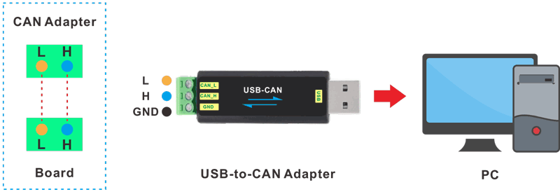
CAN connection
❷ Open the CAN application and set the baudrate to 500000 on PC.
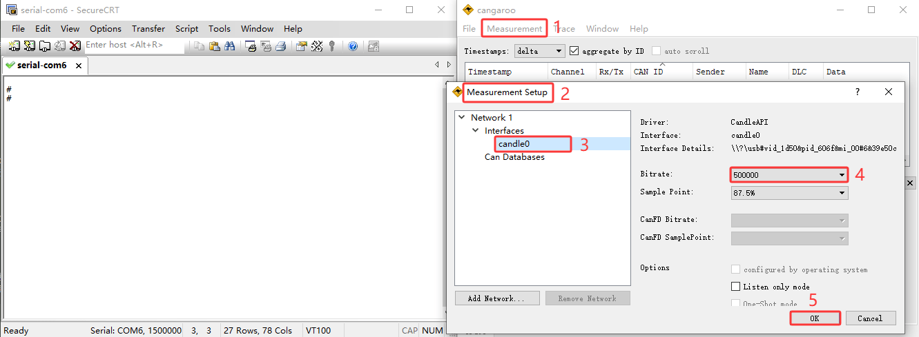
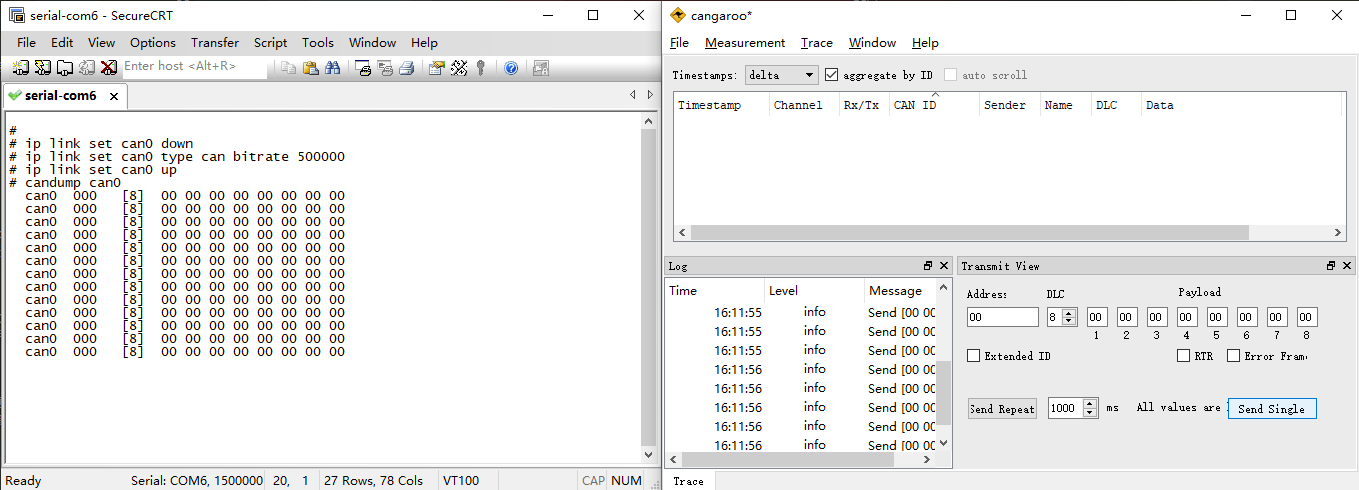
❸ Configure and enable the CAN0 on the board with a bitrate of 500000.
1ip link set can0 down
2ip link set can0 type can bitrate 500000
3ip link set can0 up
❹ Configure CAN0 as receiver.
1candump can0
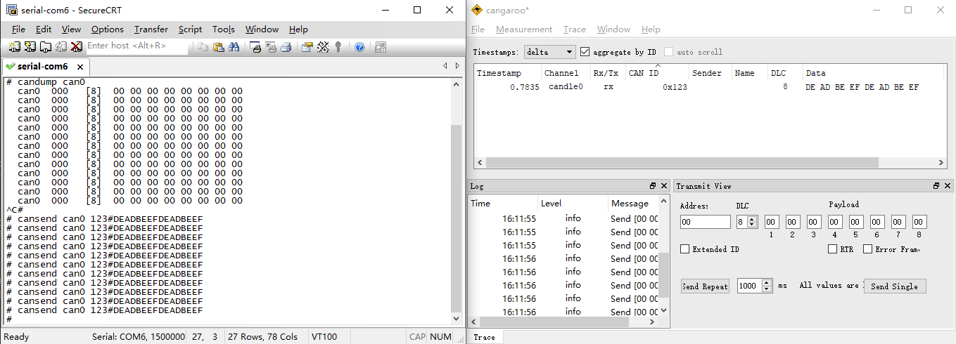
❺ Set CAN0 as Transmitter.
1cansend can0 123#DEADBEEFDEADBEEF
The tests for CAN1 are similar to those for CAN0. Simply replace can0 with can1.
3.12 SPI
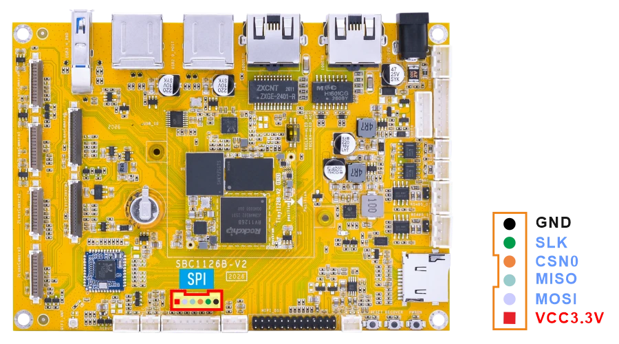
❶ Connect MOSI and MISO of SPI.
❷ SPI loopback test.
1test_spi 1 0
# test_spi 1 0
device= /dev/spidev1.0
spi mode: 0
bits per word: 8
max speed: 5000000 Hz (5000 KHz)

FF FF FF FF FF FF
40 00 00 00 00 95
FF FF FF FF FF FF
FF FF FF FF FF FF
FF FF FF FF FF FF
DE AD BE EF BA AD
F0 0D
3.13 ADC
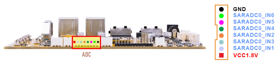
Connect the ADC pin to two different voltage levels within 0~1.8V respectively. For each level, after setting the pin to that level, execute the test command.
1cat /sys/bus/iio/devices/iio:\device0/in_voltage1_raw //test ADC1
# cat /sys/bus/iio/devices/iio:\device0/in_voltage1_raw
8
# cat /sys/bus/iio/devices/iio:\device0/in_voltage1_raw
8191
For other ADC read commands, refer to the ADC read command description below.
1cat /sys/bus/iio/devices/iio:\device0/in_voltage1_raw   //ADC1
2cat /sys/bus/iio/devices/iio:\device0/in_voltage2_raw   //ADC2
3cat /sys/bus/iio/devices/iio:\device0/in_voltage3_raw   //ADC3
4cat /sys/bus/iio/devices/iio:\device0/in_voltage4_raw   //ADC4
5cat /sys/bus/iio/devices/iio:\device0/in_voltage5_raw   //ADC5
6cat /sys/bus/iio/devices/iio:\device0/in_voltage6_raw   //ADC6
1for i in 1 2 3 4 5 6; do
2    echo -n "ADC$i: "
3    cat /sys/bus/iio/devices/iio:\device0/in_voltage${i}_raw
4done
3.14 RTC
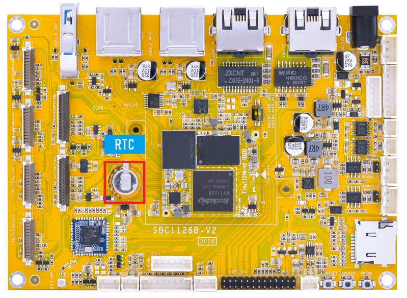
The RTC on the SBC1126B is powered by a supercapacitor.
❶ Set the system time manually.
1date -s "2026-07-08 16:22:00"
If the network is connected, the system time may be synchronized automatically to the current UTC time.
❷ Set the hardware clock to current system time.
1hwclock -w
❸ Display date and time.
1hwclock
# date -s "2026-07-08 16:22:00"
Wed Jul  8 16:22:00 UTC 2026
# hwclock -w
# hwclock
Wed Jul  8 16:22:06 2026  0.000000 seconds
# hwclock
Wed Jul  8 16:22:41 2026  0.000000 seconds
# hwclock
Wed Jul  8 16:23:04 2026  0.000000 seconds
❹ Power off. Wait a while, then reapply power. If the RTC is functioning correctly, the clock should maintain its time and keep running while the board is powered off.
1hwclock
# hwclock
Wed Jul  8 16:31:18 2026  0.000000 seconds
# hwclock
Wed Jul  8 16:31:33 2026  0.000000 seconds
# hwclock
Wed Jul  8 16:32:01 2026  0.000000 seconds
3.15 Battery Supply
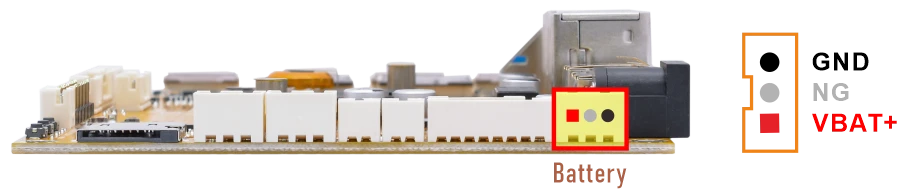
❶ Connect the Li-ion battery(7.4V) to the BAT connector, then press and hold the power button to turn on the board.
❷ Read the current battery capacity percentage.
1cat /sys/class/power_supply/cw221X-bat/capacity
❸ Read the current battery voltage.
1cat /sys/class/power_supply/cw221X-bat/voltage_now
3.16 Camera
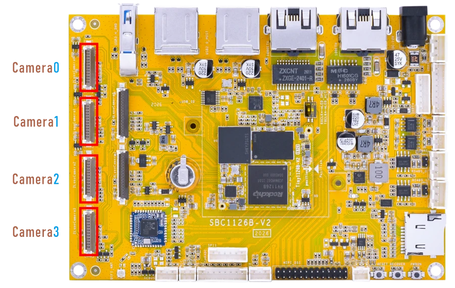
The SBC1126B provides six MIPI CSI camera interfaces, including four 2-lane MIPI CSI interfaces and two 4-lane MIPI CSI interfaces.
The 2-lane and 4-lane MIPI CSI camera modes are mutually exclusive and cannot be used simultaneously. Different camera modes require corresponding hardware configurations and firmware images.
The default camera sensors are as follows:
2-lane MIPI CSI camera: SC200AI.
4-lane MIPI CSI camera: IMX415.
To enable 4-lane cameras, remove the following resistors on the back side of the board:
Camera0(8 resistors): R5/R10/R11/R21/R22/R26/R31/R37/R39/R46
Camera1(8 resistors): R58/R60/R62/R63/R64/R65/R67/R68/R69/R70
3.16.1 2-lane Camera
Quad-Camera Preview
❶ Check the network status and obtain the Ethernet IP address of the board.
1ifconfig eth0
Serial terminal output# ifconfig eth0 eth0 Link encap:Ethernet HWaddr C6:72:C0:7F:A8:3A inet addr:192.168.0.66 Bcast:192.168.0.255 Mask:255.255.255.0 inet6 addr: fe80::c472:c0ff:fe7f:a83a/64 Scope:Link UP BROADCAST RUNNING MULTICAST MTU:1500 Metric:1 RX packets:294 errors:0 dropped:37 overruns:0 frame:0 TX packets:17 errors:0 dropped:0 overruns:0 carrier:0 collisions:0 txqueuelen:1000 RX bytes:26761 (26.1 KiB) TX bytes:3462 (3.3 KiB) Interrupt:91
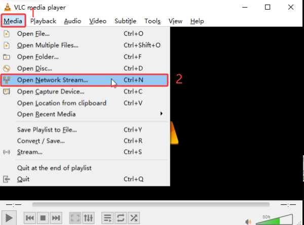
❷ Open VLC media player on the PC.

❸ Select Media -> Open Network Stream…
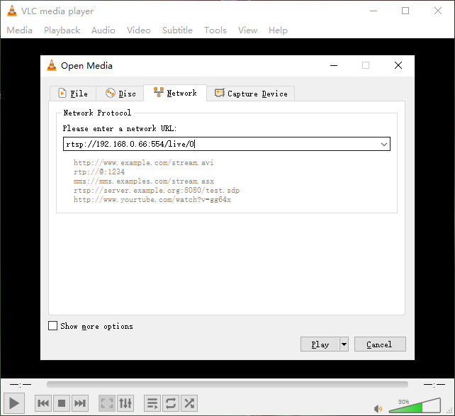
❹ Enter the following RTSP URL to preview the camera stream.
1rtsp://192.168.0.66:554/live/0
Note
Replace 192.168.0.66 with the actual Ethernet IP address of the board.
Single-Camera Preview
❶ Stop the default rkipc service.
1RkLunch-stop.sh
❷ Obtain the Ethernet IP address and check the network interface status.
1udhcpc
2ifconfig eth0
Serial terminal output# udhcpc udhcpc: started, v1.36.1 udhcpc: broadcasting discover udhcpc: broadcasting select for 192.168.0.159, server 192.168.0.1 udhcpc: lease of 192.168.0.159 obtained from 192.168.0.1, lease time 86400 deleting routers adding dns 192.168.0.1 # # ifconfig eth0 eth0 Link encap:Ethernet HWaddr E6:D1:34:7F:C1:B2 inet addr:192.168.0.159 Bcast:192.168.0.255 Mask:255.255.255.0 inet6 addr: fe80::e4d1:34ff:fe7f:c1b2/64 Scope:Link UP BROADCAST RUNNING MULTICAST MTU:1500 Metric:1 RX packets:653 errors:0 dropped:83 overruns:0 frame:0 TX packets:19 errors:0 dropped:0 overruns:0 carrier:0 collisions:0 txqueuelen:1000 RX bytes:54141 (52.8 KiB) TX bytes:3322 (3.2 KiB) Interrupt:91
❸ Start the camera demo.
1sample_demo_four_camera
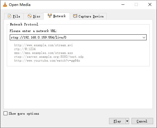
❹ Open VLC media player on the PC.
❺ Select Media -> Open Network Stream…
❻ Enter the RTSP URL to Preview the Camera Stream.
Camera01rtsp://192.168.0.159:554/live/0
 Camera1
1rtsp://192.168.0.159:554/live/2
Camera21rtsp://192.168.0.159:554/live/4
Camera31rtsp://192.168.0.159:554/live/6
Note
Replace 192.168.0.159 with the actual Ethernet IP address of the board.
3.16.2 4-lane Camera
Verify that the resistors on the back of the development board have been removed.
Dual-Camera Preview
❶ Check the network status and obtain the Ethernet IP address of the board.
1ifconfig eth0
Serial terminal output# ifconfig eth0 eth0 Link encap:Ethernet HWaddr 02:27:CF:6A:93:00 inet addr:192.168.0.236 Bcast:192.168.0.255 Mask:255.255.255.0 inet6 addr: fe80::27:cfff:fe6a:9300/64 Scope:Link UP BROADCAST RUNNING MULTICAST MTU:1500 Metric:1 RX packets:79 errors:0 dropped:9 overruns:0 frame:0 TX packets:17 errors:0 dropped:0 overruns:0 carrier:0 collisions:0 txqueuelen:1000 RX bytes:8394 (8.1 KiB) TX bytes:4006 (3.9 KiB) Interrupt:90
❷ Open VLC media player on the PC.
❸ Select Media -> Open Network Stream…
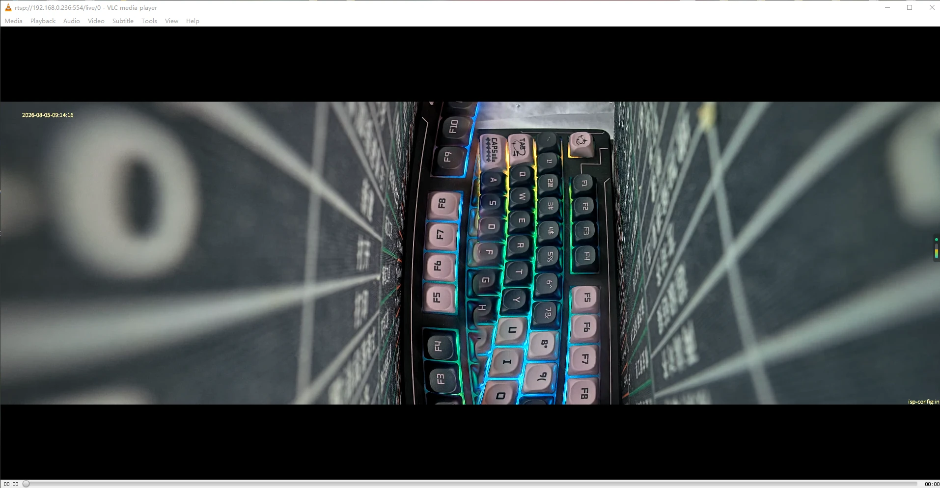
❹ Enter the following RTSP URL to preview the camera stream.
1rtsp://192.168.0.236:554/live/0
Note
Replace 192.168.0.236 with the actual Ethernet IP address of the board.
Single-Camera Preview
❶ Stop the default rkipc service.
1RkLunch-stop.sh
❷ Obtain the Ethernet IP address and check the network interface status.
1udhcpc
2ifconfig eth0
Serial terminal output# udhcpc udhcpc: started, v1.36.1 udhcpc: broadcasting discover udhcpc: broadcasting select for 192.168.0.236, server 192.168.0.1 udhcpc: lease of 192.168.0.236 obtained from 192.168.0.1, lease time 86400 deleting routers adding dns 192.168.0.1 # ifconfig eth0 eth0 Link encap:Ethernet HWaddr 02:27:CF:6A:93:00 inet addr:192.168.0.236 Bcast:192.168.0.255 Mask:255.255.255.0 inet6 addr: fe80::27:cfff:fe6a:9300/64 Scope:Link UP BROADCAST RUNNING MULTICAST MTU:1500 Metric:1 RX packets:273 errors:0 dropped:34 overruns:0 frame:0 TX packets:21 errors:0 dropped:0 overruns:0 carrier:0 collisions:0 txqueuelen:1000 RX bytes:25252 (24.6 KiB) TX bytes:4278 (4.1 KiB) Interrupt:90
❸ Start the camera demo.
1sample_demo_dual_camera -s 0 -W 1920 -H 1080 -w 720 -h 576 -f 30 -r 0 -s 1 -W 1920 -H 1080 -w 720 -h 576 -f 30 -r 0 -n 0 -b 1
❹ Open VLC media player on the PC.
❺ Select Media -> Open Network Stream…
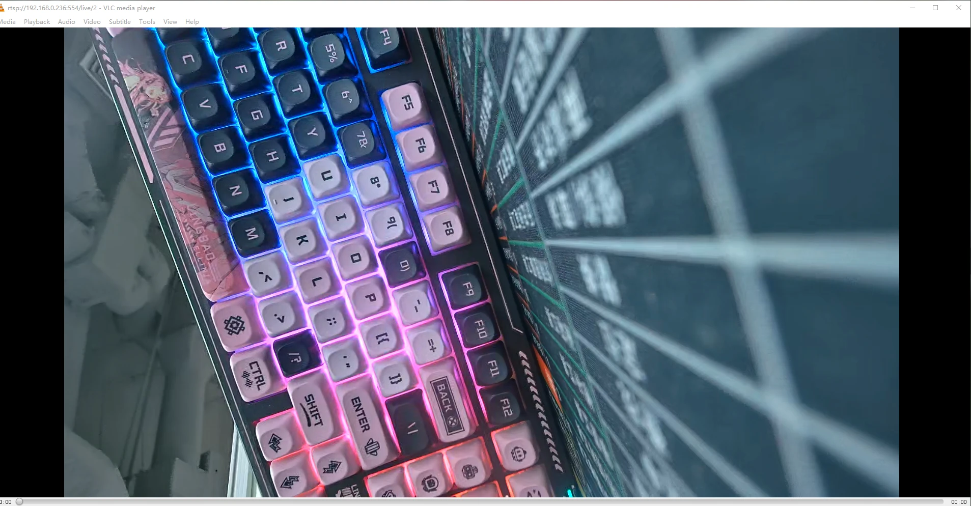
❻ Enter the RTSP URL to Preview the Camera Stream.
Camera01rtsp://192.168.0.236:554/live/0
Camera11rtsp://192.168.0.236:554/live/2
Note
Replace 192.168.0.236 with the actual Ethernet IP address of the board.
3.17 Video Playback
Video playback can be tested using the simple_vdec_bind_vo command.
1simple_vdec_bind_vo -i /tmp/sda1/testh264.h264
# simple_vdec_bind_vo -i /tmp/sda1/testh264.h264
param list: w = 1920, h = 1080, i = /tmp/sda1/testh264.h264, b = 1
rockit_load start
v4l2_tx probe successv4l2_rx_probe success
rockit_load end
rockit log path (null), log_size = 0
log_file = (nil)
(null)           17:33:44-604 {log_level_init    :209}

 please use echo name=level > /tmp/rt_log_level set log level
        name: all cmpi mb sys vdec venc rgn vpss vgs tde avs wbc vo vi ai ao aenc adec
        log_level: 0 1 2 3 4 5 6

rockit default level 4, can use export rt_log_level=x, x=0,1,2,3,4,5,6 change
(null)           17:33:44-605 {read_log_level    :083} text is all=4
(null)           17:33:44-605 {read_log_level    :085} module is all, log_level is 4
(null)           17:33:44-605 {dump_version      :060} ---------------------------------------------------------
(null)           17:33:44-605 {dump_version      :061} rockit version: git-b85f3c523 Mon Jan 26 09:47:22 2026 +0800
(null)           17:33:44-605 {dump_version      :062} rockit building: built-Chu 2026-01-27 09:45:41
(null)           17:33:44-605 {dump_version      :063} ---------------------------------------------------------
(null)           17:33:44-605 {monitor_log_level :141} #Start monitor_log_level thread, arg:(nil)
vsys dev open 4
load library(librga.so) in releative path
mpp[1041]: mpp_info: mpp version: d7dd00e4f author: Herman Chen  2026-02-13 fix[h265d]: Fix invalid hvcc data crash on seek
mpp[1041]: hal_264d_com: control info: fmt 0, w 1920, h 1080
mpp[1041]: mpp_dec: mpp_dec_proc_cfg found MPP_DEC_SET_FRAME_INFO fmt 0
mpp[1041]: mpp_buf_slot: mismatch h_stride_by_pixel 1984 - 1920
mpp[1041]: mpp_buf_slot: mismatch h_stride_by_byte 1984 - 1920
Command explanation
simple_vdec_bind_vo: Video decoding and display test tool.-i: Specifies the input video file./mnt/udisk/testh264.h264: Input H.264 file path.
Note
This command supports H.264 elementary stream files, such as .h264 files. Standard MP4 files are not supported.