4. Buildroot Application
In the Buildroot rockit version, the rkipc service starts automatically after system boot. To avoid conflicts during function tests, stop the rkipc service before testing other functions.
1RkLunch-stop.sh
1RkLunch.sh
4.1 Serial Terminal
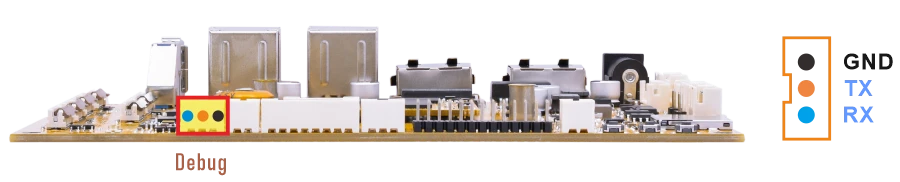
❶ Connect the USB-to-serial module to the PC and connect the other end to the Debug UART interface on the board.
❷ Open a serial terminal tool on the PC, select the corresponding serial port, and set the baud rate to 1500000.
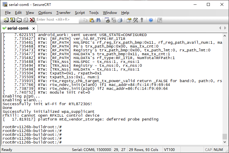
❸ Power on the board and check whether the boot log is displayed in the serial terminal.
4.2 Display
Buildroot provides two variants: GStreamer and Rockit. The display output may vary depending on which firmware version is used.
4.2.1 GStreamer
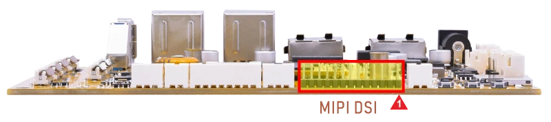
Connect the board and MIPI LCD (default 800×1280 @60Hz), then start up.

4.2.2 Rockit
In the Rockit version, the system does not display the desktop by default after boot. After flashing the corresponding firmware image and connecting the supported cameras before power-on, the system automatically starts the camera preview. The display output shows the stitched preview image from the connected camera channels. If no camera is connected or the connected camera does not match the flashed firmware image, the display remains black after boot.
4.3 USB
4.3.1 USB3.0 DRD
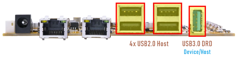
The SBC1126B USB3.0 DRD supports both Host and Device roles, with Device as the default configuration for image flashing/upgrading. It can be switched to host mode by command, after which it supports peripherals such as mouse, keyboards, and USB flash drives.
1echo host > /sys/kernel/debug/usb/21500000.usb/mode
In USB host mode, when a USB flash drive is connected, it is mounted automatically. The current USB connection speed can be checked in the kernel log.
When the device operates in USB2.0 mode, the log usually shows high-speed.
When the device operates in USB3.0 mode, the log usually shows SuperSpeed.
1echo device > /sys/kernel/debug/usb/21500000.usb/mode
4.3.2 USB2.0 Host
The USB2.0 Host can connect peripherals such as mouse, keyboards, and flash drives.
After a USB flash drive is connected, it will be mounted automatically. Check the mounted path.
1df -h
root@rv1126b-buildroot:/# df -h
Filesystem      Size  Used Avail Use% Mounted on
/dev/root       5.9G  445M  5.3G   8% /
devtmpfs        959M     0  959M   0% /dev
tmpfs           987M  548K  986M   1% /run
tmpfs           987M  212K  987M   1% /var/log
tmpfs           987M     0  987M   0% /dev/shm
tmpfs           987M  136K  987M   1% /tmp
/dev/mmcblk0p7  124M  5.3M  118M   5% /oem
/dev/mmcblk0p8  936M  292K  936M   1% /userdata
/dev/sda1        58G   57G  1.9G  97% /mnt/udisk
/dev/mmcblk1p1   30G  4.6G   26G  16% /mnt/sdcard
4.4 Audio
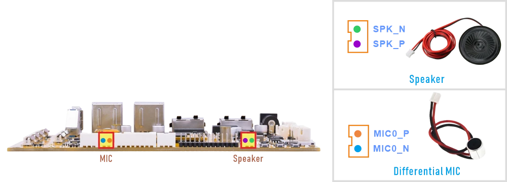
4.4.1 Audio Output
❶ Connect the Speaker to the connector (2-pin/2.0mm pitch)
❷ Set the DAC digital volume.
1amixer -c 0 cset name='DAC Digital Volume' 250,250
❸ Play the audio file.
Execute command according to the actual audio file path, eg. /mnt/udisk1/video/music/2.wav
1aplay -D hw:0,0 /mnt/udisk1/video/music/2.wav
4.4.2 Audio Input
- SBC1126B supports MIC recording and Loopback.
MIC recordingcaptures outside sounds (e.g., voice) for storage, transmission, or voice commands.Loopbackcaptures the device’s own playback as a reference signal. It is primarily used for Acoustic Echo Cancellation (AEC) and audio monitoring. It is a tool for signal processing, not an audio recording of the environment.
Note
For the Rockit version, the audio recording test may conflict with the rkipc service. Before performing the audio input test, stop rkipc first:
1RkLunch-stop.sh
To start rkipc again after the test:
1RkLunch.sh
❶ Connect the MIC to the connector (2-pin/2.0mm pitch).
❷ Execute the commands.
1amixer -c 0 cset name='SAI2 Receive PATH0 Source Select' 'From SDI0'   //Select MIC0 as the recording input source
2amixer -c 0 cset name='ACodec Digital Gain Volume' 100   //Set the audio codec digital gain
3arecord -D hw:0,0 -f cd -t wav test.wav   //Record audio from MIC0
4aplay -D hw:0,0 test.wav   //Play the recorded audio through the speaker
Serial terminal outputroot@rv1126b-buildroot:/# amixer -c 0 cset name='SAI2 Receive PATH0 Source Select' 'From SDI0' numid=29,iface=MIXER,name='SAI2 Receive PATH0 Source Select' ; type=ENUMERATED,access=rw------,values=1,items=4 ; Item #0 'From SDI0' ; Item #1 'From SDI1' ; Item #2 'From SDI2' ; Item #3 'From SDI3' : values=0 root@rv1126b-buildroot:/# amixer -c 0 cset name='ACodec Digital Gain Volume' 100 numid=44,iface=MIXER,name='ACodec Digital Gain Volume'c Digital Gain Volume' 100 ; type=INTEGER,access=rw---R--,values=1,min=0,max=127,step=0 : values=100 | dBscale-min=-95.00dB,step=0.75dB,mute=0 root@rv1126b-buildroot:/# root@rv1126b-buildroot:/# arecord -D hw:0,0 -f cd -t wav test.wav Recording WAVE 'test.wav' : Signed 16 bit Little Endian, Rate 44100 Hz, Stereo ^CAborted by signal Interrupt... root@rv1126b-buildroot:/# root@rv1126b-buildroot:/# aplay -D hw:0,0 test.wav Playing WAVE 'test.wav' : Signed 16 bit Little Endian, Rate 44100 Hz, Stereo
❶ Audio input configuration.
1amixer -c 0 cset name='SAI2 Receive PATH0 Source Select' 'From SDI0'   //recording input source
2amixer -c 0 cset name='SAI2 Receive PATH1 Source Select' 'From SDI1'   //Loopback reference input
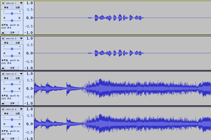
❷ Record 4-channel audio.
1aplay -D hw:0,0 /mnt/udisk1/video/music/2.wav & arecord -D hw:0,0 -f S16_LE -r 44100 -c 4 /test.wav
❸ Copy the recorded file to the PC and check the audio channels with audio software.
4.5 Ethernet
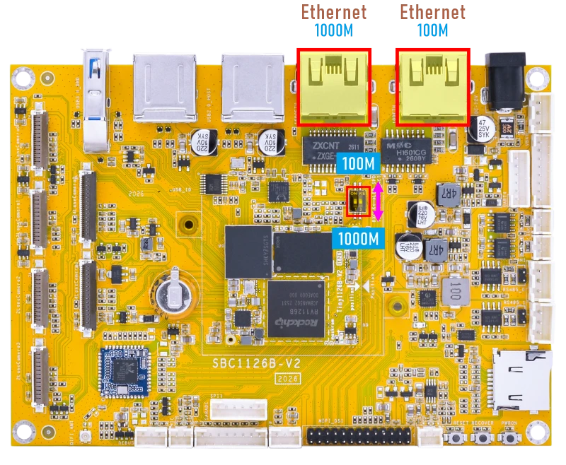
The 100M Ethernet and 1000M Ethernet interfaces on the SBC1126B are multiplexed and cannot be used at the same time. When switching between them, the corresponding firmware image must be updated in software, and the hardware selection must also be changed using the DIP switch on the development board.
DTS Configuration Switching Instructions File path kernel-6.1\arch\arm64\boot\dts\rockchip\boardcon-sbc1126b.dts
//#include "boardcon-sbc1126b-gephy.dtsi" //1000M
#include "boardcon-sbc1126b-fephy.dtsi"   //100M
#include "boardcon-sbc1126b-gephy.dtsi"    //1000M
//#include "boardcon-sbc1126b-fephy.dtsi"  //100M
4.5.1 100M Ethernet
❶ Connect the network cable to the 100M Ethernet port, and set the DIP switch to the 100M position.
root@rv1126b-buildroot:/#
[ 2239.711481] rk_gmac-dwmac 21c70000.ethernet eth0: Link is Up - 100Mbps/Full - flow control rx/tx
[ 2239.711505] IPv6: ADDRCONF(NETDEV_CHANGE): eth0: link becomes ready
❷ View the status of the network interface.
1ifconfig eth0
root@rv1126b-buildroot:/# ifconfig eth0
eth0      Link encap:Ethernet  HWaddr 2E:CD:2F:8A:A1:64
          inet addr:192.168.0.175  Bcast:192.168.0.255  Mask:255.255.255.0
          inet6 addr: fe80::b786:555a:8922:5eb2/64 Scope:Link
          UP BROADCAST RUNNING MULTICAST  MTU:1500  Metric:1
          RX packets:231 errors:0 dropped:28 overruns:0 frame:0
          TX packets:11 errors:0 dropped:0 overruns:0 carrier:0
          collisions:0 txqueuelen:1000
          RX bytes:20498 (20.0 KiB)  TX bytes:1410 (1.3 KiB)
          Interrupt:79
❸ Test network connectivity.
1ping -I eth0 www.armdesigner.com
root@rv1126b-buildroot:/# ping -I eth0 www.armdesigner.com
PING d3dsoj86mhwkk6.cloudfront.net (108.138.246.8) from 192.168.0.175 eth0: 56(84) bytes of data.
64 bytes from www.armdesigner.com (108.138.246.8): icmp_seq=1 ttl=246 time=155 ms
64 bytes from www.armdesigner.com (108.138.246.8): icmp_seq=2 ttl=246 time=155 ms
64 bytes from www.armdesigner.com (108.138.246.8): icmp_seq=3 ttl=246 time=151 ms
64 bytes from www.armdesigner.com (108.138.246.8): icmp_seq=4 ttl=246 time=155 ms
64 bytes from www.armdesigner.com (108.138.246.8): icmp_seq=5 ttl=246 time=154 ms
64 bytes from www.armdesigner.com (108.138.246.8): icmp_seq=6 ttl=246 time=150 ms
^C
--- d3dsoj86mhwkk6.cloudfront.net ping statistics ---
6 packets transmitted, 6 received, 0% packet loss, time 5007ms
rtt min/avg/max/mdev = 150.276/153.243/154.972/1.845 ms
4.5.2 1000M Ethernet
❶ Connect the network cable to the 1000M Ethernet port, and set the DIP switch to the 1000M position.
root@rv1126b-buildroot:/#
[   80.044336] rk_gmac-dwmac 21c70000.ethernet eth0: Link is Up - 1Gbps/Full - flow control rx/tx
[   80.044406] IPv6: ADDRCONF(NETDEV_CHANGE): eth0: link becomes ready
❷ View the status of the network interface.
1ifconfig eth0
❸ Test network connectivity.
1ping -I eth0 www.armdesigner.com
4.6 SD Card
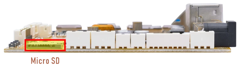
After the micro SD card is inserted and recognized successfully, it will be mounted automatically. Run the following command to check the mount path of the SD card.
1df -h
root@rv1126b-buildroot:/# df -h
Filesystem      Size  Used Avail Use% Mounted on
/dev/root       5.9G  445M  5.3G   8% /
devtmpfs        959M     0  959M   0% /dev
tmpfs           987M  548K  986M   1% /run
tmpfs           987M  212K  987M   1% /var/log
tmpfs           987M     0  987M   0% /dev/shm
tmpfs           987M  136K  987M   1% /tmp
/dev/mmcblk0p7  124M  5.3M  118M   5% /oem
/dev/mmcblk0p8  936M  292K  936M   1% /userdata
/dev/sda1        58G   57G  1.9G  97% /mnt/udisk
/dev/mmcblk1p1   30G  4.6G   26G  16% /mnt/sdcard
4.7 WiFi & Bluetooth
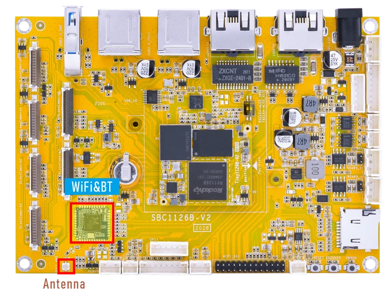
4.7.1 WiFi
❶ Connect the WiFi antenna.
❷ Check the Wi-Fi device information.
1ifconfig wlan0
root@rv1126b-buildroot:/# ifconfig wlan0
wlan0     Link encap:Ethernet  HWaddr 84:FC:14:F9:69:64
          UP BROADCAST MULTICAST  MTU:1500  Metric:1
          RX packets:0 errors:0 dropped:0 overruns:0 frame:0
          TX packets:0 errors:0 dropped:0 overruns:0 carrier:0
          collisions:0 txqueuelen:1000
          RX bytes:0 (0.0 B)  TX bytes:0 (0.0 B)
❸ Scan for available WiFi hotspots.
1iwlist wlan0 scan
1wpa_cli -i wlan0 scan
2wpa_cli -i wlan0 scan_results
❹ Connect hotspot.
1wifi-connect.sh SSID PSK //'SSID': user SSID, 'PSK': password
After connected, check the network status and ping URL to test.
1ifconfig wlan0
2ping -I wlan0 www.armdesigner.com
4.7.2 Bluetooth
By default, the device is configured to operate as a Bluetooth speaker. The following steps describe how to pair with and connect to a device:
❶ Start the BlueALSA A2DP sink service.
1bluealsa -p a2dp-sink &
root@rv1126b-buildroot:/# bluealsa -p a2dp-sink &
[1] 1867
root@rv1126b-buildroot:/# bluealsa: [1867] D: storage.c:84: Initializing persistent storage: /var/lib/bluealsa
bluealsa: [1867] D: main.c:604: Starting main dispatching loop
bluealsa: [1867] D: main.c:114: Acquired D-Bus service name: org.bluealsa
bluealsa: [1867] D: bluealsa-dbus.c:392: Registering D-Bus manager: /org/bluealsa
[ 5741.163059] Bluetooth: hu 000000005f39388b retransmitting 1 pkts
[ 5741.163991] rtk_btcoex: BTCOEX hci_rev 0xaaa8
[ 5741.163998] rtk_btcoex: BTCOEX lmp_subver 0x2df5
bluealsa: [1867] D: bluez.c:783: Registering battery provider: /org/bluez/hci0/battery
bluealsa: [1867] D: bluez.c:598: Creating media endpoint object: /org/bluez/hci0/A2DP/SBC/sink/1
bluealsa: [1867] D: bluez.c:509: Registering media endpoint: /org/bluez/hci0/A2DP/SBC/sink/1
bluealsa: [1867] D: bluez.c:598: Creating media endpoint object: /org/bluez/hci0/A2DP/SBC/sink/2
bluealsa: [1867] D: bluez.c:509: Registering media endpoint: /org/bluez/hci0/A2DP/SBC/sink/2
❷ Enter the Bluetooth control tool.
1bluetoothctl
root@rv1126b-buildroot:/# bluetoothctl
hci0 new_settings: powered bondable ssp br/edr le secure-conn
Agent registered
[CHG] Controller 84:FC:14:F9:69:65 Pairable: yes
[bluetooth]#
❸ Enable Bluetooth and set it to discoverable mode.
1power on
2discoverable on
[bluetooth]# power on
Changing power on succeeded
[bluetooth]# discoverable on
[bluetooth]# [ 5813.299958] Bluetooth: hu 000000005f39388b retransmitting 1 pkts
hci0 new_settings: powered connectable bondable ssp br/edr le secure-conn
hci0 new_settings: powered connectable discoverable bondable ssp br/edr le secure-conn
Changing discoverable on succeeded
[CHG] Controller 84:FC:14:F9:69:65 Discoverable: yes
[bluetooth]#
After this step, the Bluetooth device can be discovered by the phone.
❹ Pair and connect the Bluetooth device.
On the phone, find the Bluetooth device named BlueZ 5.77 in the Bluetooth device list, then tap it to pair and connect.
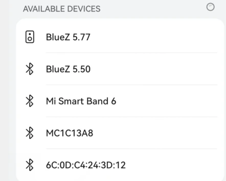
If a pairing confirmation message appears, confirm it on both the phone and the board.
[bluetooth]# [  190.276160] rtk_btcoex: hci accept conn req
[  190.474589] rtk_btcoex: connected, handle 0002, status 0x00
[  190.474615] rtk_btcoex: Page success
[  190.522637] rtk_btcoex: io capability request
hci0 A8:35:12:9A:EB:4D type BR/EDR connected eir_len 11
[CHG] Device A8:35:12:9A:EB:4D INFO: 0x000f (15)
[CHG] Device A8:35:12:9A:EB:4D Connected: yes
Request confirmation
[agent] Confirm passkey 406213 (yes/no): yes
[liuy]# [  195.146220] rtk_btcoex: link key notify
hci0 new_link_key A8:35:12:9A:EB:4D type 0x05 pin_len 0 store_hint 1
[liuy]# [  195.173161] rtk_btcoex: l2cap op 2, len 16, out 0
hci0 A8:35:12:9A:EB:4D type BR/EDR disconnected with reason 0
[  199.550019] rtk_btcoex: process disconn complete event.
[CHG] Device A8:35:12:9A:EB:4D INFO: 0x000d (13)
[CHG] Device A8:35:12:9A:EB:4D Connected: no
[CHG] Device A8:35:12:9A:EB:4D Reason: 0x0000 (0)
[bluetooth]# [  206.851770] rtk_btcoex: hci accept conn req
[  207.047726] rtk_btcoex: connected, handle 0003, status 0x00
[  207.047752] rtk_btcoex: Page success
hci0 A8:35:12:9A:EB:4D type BR/EDR connected eir_len 11
[CHG] Device A8:35:12:9A:EB:4D INFO: 0x000f (15)
[CHG] Device A8:35:12:9A:EB:4D Connected: yes
[liuy]# Authorize service
[agent] Authorize service 0000110d-0000-1000-8000-00805f9b34fb (yes/no): yes
[liuy]# [  209.640679] rtk_btcoex: l2cap op 3, len 20, out 1
Check the log output to confirm the MAC address. In this example, the MAC address of the mobile phone is A8:35:12:9A:EB:4D.
❺ Exit bluetoothctl.
1exit
❻ Start Bluetooth audio playback.
1bluealsa-aplay A8:35:12:9A:EB:4D &
[liuy]# exit
root@rv1126b-buildroot:/# [  252.758958] rtk_btcoex: update_hid_active_state: handle 0x0003, interval 400
[  252.759004] rtk_btcoex: HID not connected, nothing to be down
root@rv1126b-buildroot:/# bluealsa-aplay A8:35:12:9A:EB:4D &
[2] 1485
root@rv1126b-buildroot:/#
After the Bluetooth connection is established, play audio on the phone. The audio should be output from the board.
4.8 IR

❶ Connect the IR receiver.
❷ Enable IR debug logs.
1echo 1 > /sys/module/rockchip_pwm_remotectl/parameters/code_print
❸ Press remote button, key value printed to log.
root@rv1126b-buildroot:/# echo 1 > /sys/module/rockchip_pwm_remotectl/parameters/code_print
root@rv1126b-buildroot:/#
[ 1345.994471] USERCODE=0x1818
[ 1346.021609] RMC_GETDATA=98
[ 1347.228038] USERCODE=0x1818
[ 1347.255198] RMC_GETDATA=99
[ 1347.849855] USERCODE=0x3030
[ 1347.875982] RMC_GETDATA=34
[ 1348.437214] USERCODE=0x1818
[ 1348.464347] RMC_GETDATA=9b
[ 1350.801900] USERCODE=0x1818
4.9 RS485
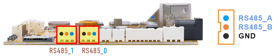
❶ Connect PC and board with USB-to-RS485 adapter.
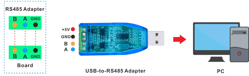
RS485 connection
❷ Open two serial terminal windows. Set the debug serial port baud rate to 1500000, and set the RS485 serial port baud rate to 115200.
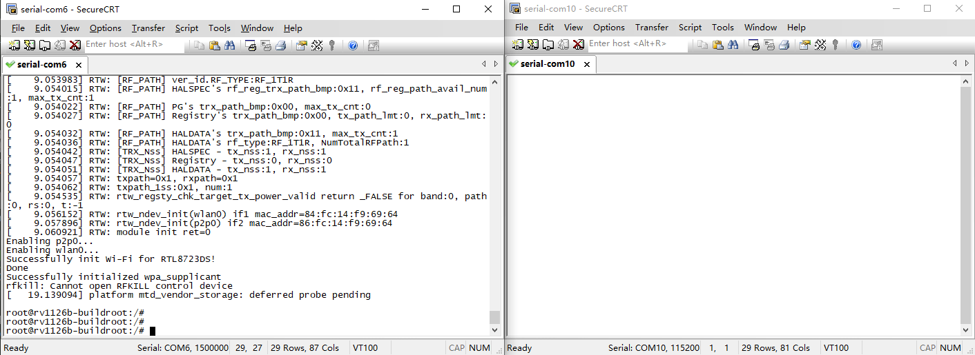
❸ Execute command on the terminal serial port of board to test RS485_0.
1com /dev/ttyS5 115200 8 0 1
❹ Input character to test RS485 communication.
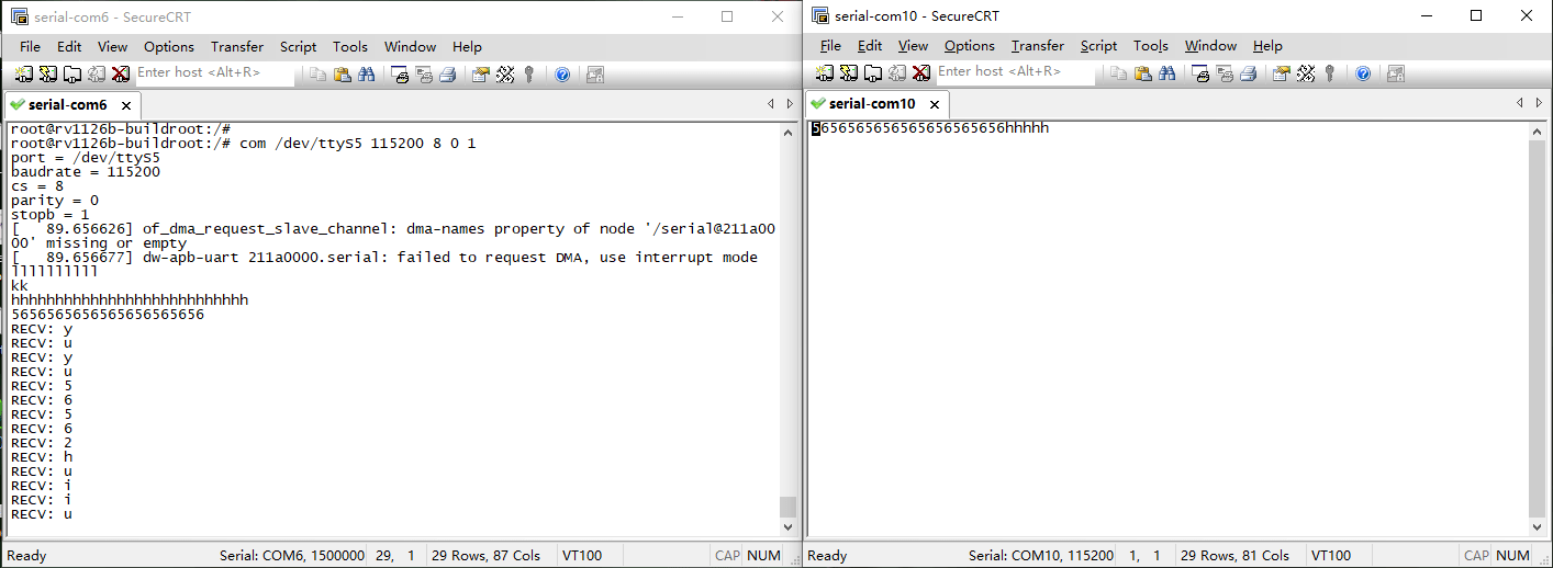
❺ Press Ctrl + C to exit RS485_0 testing.
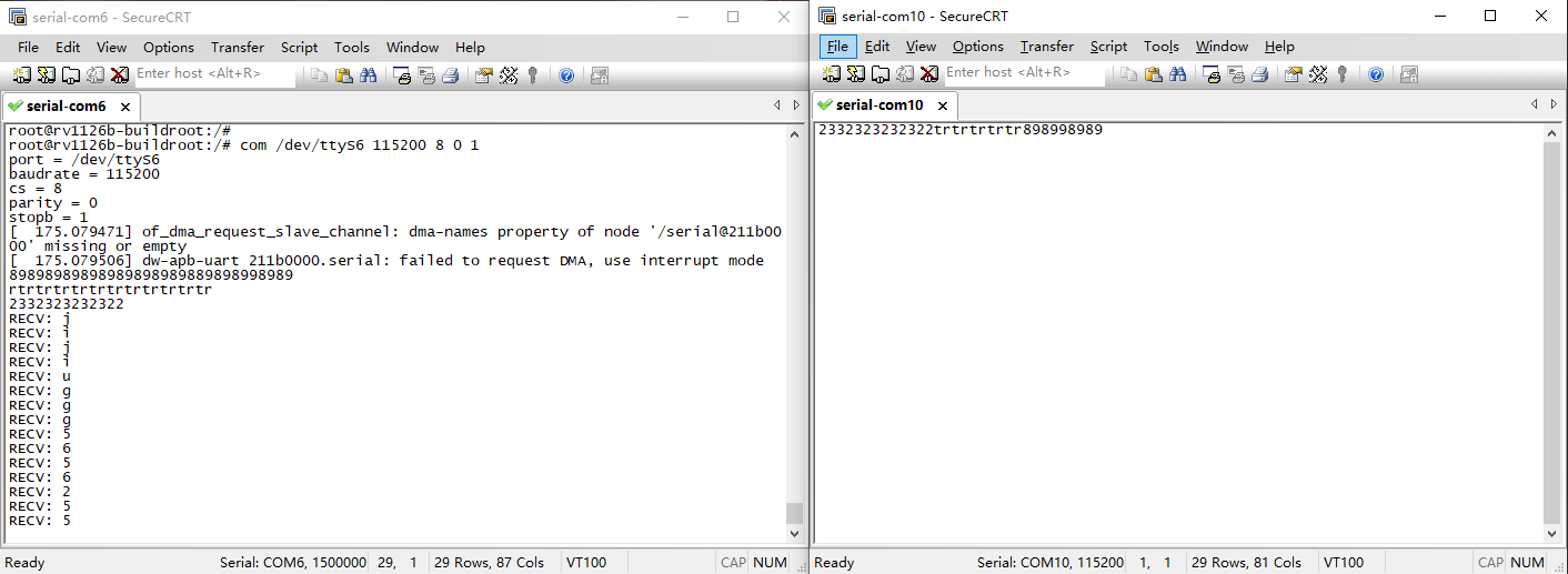
❻ Test RS485_1.
1com /dev/ttyS6 115200 8 0 1
4.10 UART
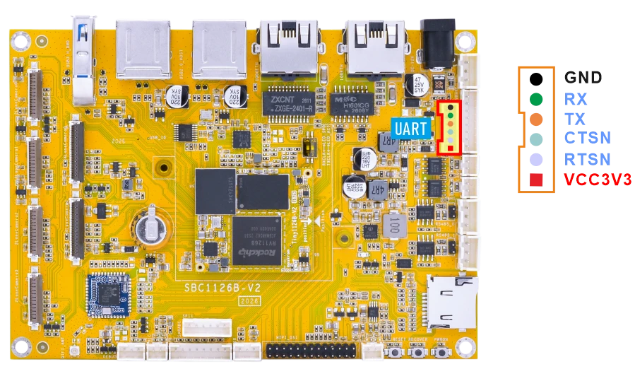
❶ Connect RX and TX of UART.
❷ Execute command and input character to test.
1com /dev/ttyS4 115200 8 0 1
root@rv1126b-buildroot:/# com /dev/ttyS4 115200 8 0 1
port = /dev/ttyS4
baudrate = 115200
cs = 8
parity = 0
stopb = 1
12345678
RECV: 12345678
abcdefg
RECV: abcdefg
4.11 CAN
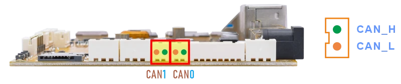
❶ Connect PC and board with USB-to-CAN adapter.
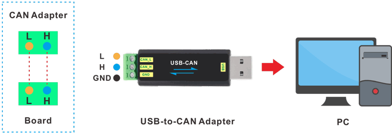
CAN connection
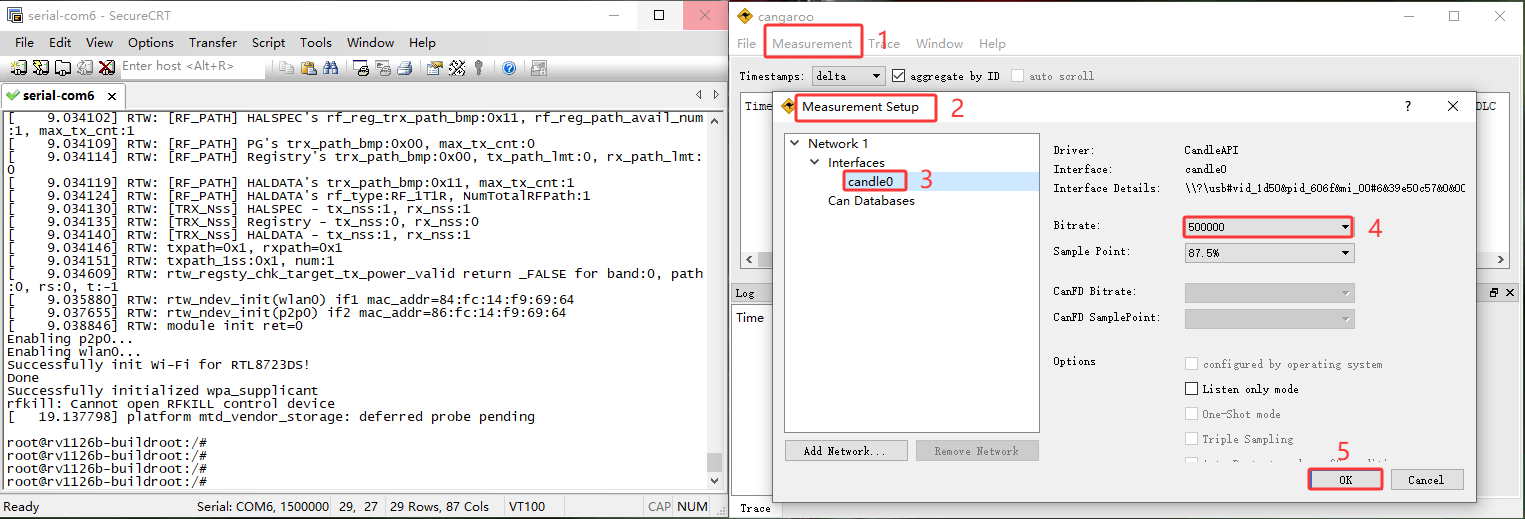
❷ Open the CAN application and set the baudrate to 500000 on PC.
❸ Configure and enable the CAN0 on the board with a bitrate of 500000.
1ip link set can0 down
2ip link set can0 type can bitrate 500000
3ip link set can0 up
❹ Configure CAN0 as receiver.
1candump can0
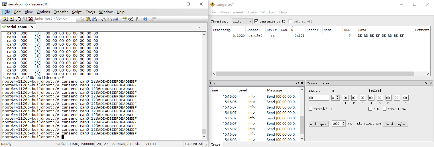
❺ Set CAN0 as Transmitter.
1cansend can0 123#DEADBEEFDEADBEEF
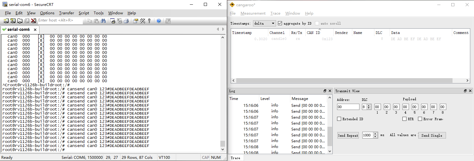
The tests for CAN1 are similar to those for CAN0. Simply replace can0 with can1.
4.12 SPI
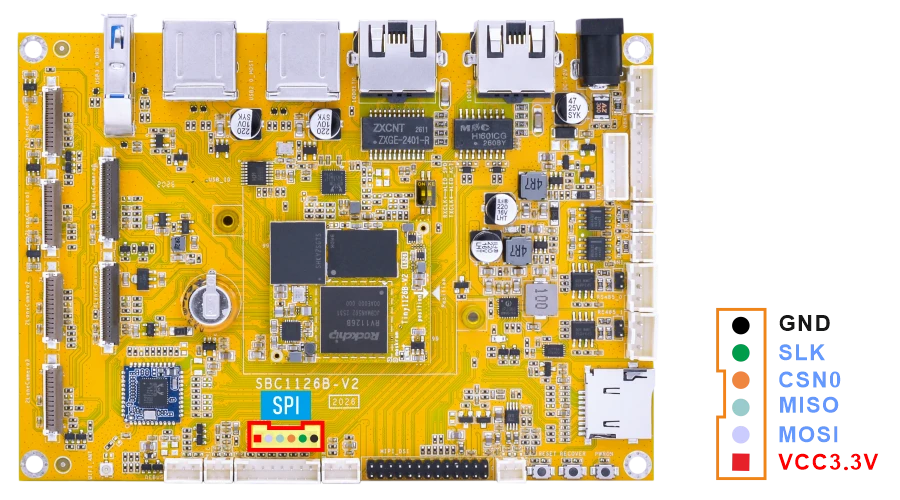
❶ Connect MOSI and MISO of SPI.
❷ SPI loopback test.
1test_spi 1 0
root@rv1126b-buildroot:/# test_spi 1 0
device= /dev/spidev1.0
bits per word: 8
max speed: 5000000 Hz (5000 KHz)

FF FF FF FF FF FF
40 00 00 00 00 95
FF FF FF FF FF FF
FF FF FF FF FF FF
FF FF FF FF FF FF
DE AD BE EF BA AD
F0 0D
4.13 ADC
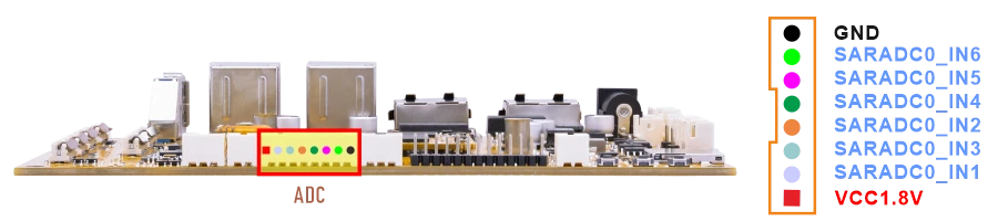
Connect the ADC pin to two different voltage levels within 0~1.8V respectively. For each level, after setting the pin to that level, execute the test command.
1cat /sys/bus/iio/devices/iio:\device0/in_voltage1_raw //test ADC1
root@rv1126b-buildroot:/# cat /sys/bus/iio/devices/iio:\device0/in_voltage1_raw
8191
root@rv1126b-buildroot:/# cat /sys/bus/iio/devices/iio:\device0/in_voltage1_raw
14
For other ADC read commands, refer to the ADC read command description below.
1cat /sys/bus/iio/devices/iio:\device0/in_voltage1_raw   //ADC1
2cat /sys/bus/iio/devices/iio:\device0/in_voltage2_raw   //ADC2
3cat /sys/bus/iio/devices/iio:\device0/in_voltage3_raw   //ADC3
4cat /sys/bus/iio/devices/iio:\device0/in_voltage4_raw   //ADC4
5cat /sys/bus/iio/devices/iio:\device0/in_voltage5_raw   //ADC5
6cat /sys/bus/iio/devices/iio:\device0/in_voltage6_raw   //ADC6
1for i in 1 2 3 4 5 6; do
2    echo -n "ADC$i: "
3    cat /sys/bus/iio/devices/iio:\device0/in_voltage${i}_raw
4done
4.14 RTC
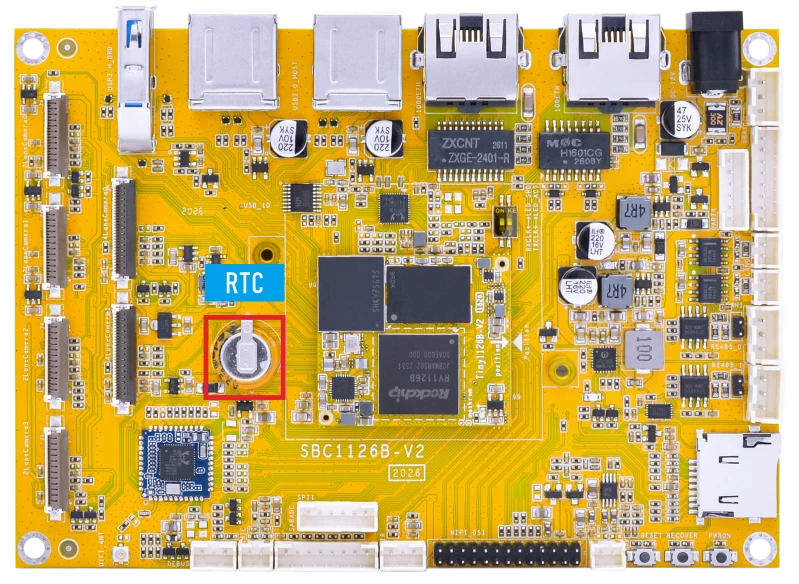
The RTC on the SBC1126B is powered by a supercapacitor.
❶ Set the system time manually.
1date -s "2026-05-21 16:00:00"
If the network is connected, the system time may be synchronized automatically to the current UTC time.
❷ Set the hardware clock to current system time.
1hwclock -w
❸ Display date and time.
1hwclock
root@rv1126b-buildroot:/# date -s "2026-05-21 16:00:00"
Thu May 21 16:00:00 UTC 2026
root@rv1126b-buildroot:/# hwclock -w
root@rv1126b-buildroot:/# hwclock
Thu May 21 16:00:07 2026  0.000000 seconds
root@rv1126b-buildroot:/# hwclock
Thu May 21 16:00:24 2026  0.000000 seconds
❹ Power off. Wait a while, then reapply power. If the RTC is functioning correctly, the clock should maintain its time and keep running while the board is powered off.
1hwclock
root@rv1126b-buildroot:/# hwclock
Thu May 21 16:11:16 2026  0.000000 seconds
root@rv1126b-buildroot:/# hwclock
Thu May 21 16:11:33 2026  0.000000 seconds
root@rv1126b-buildroot:/# hwclock
Thu May 21 16:12:06 2026  0.000000 seconds
4.15 Battery Supply
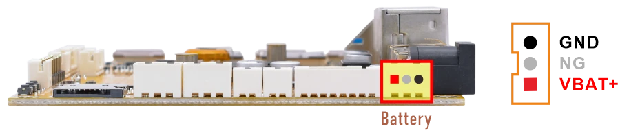
❶ Connect the Li-ion battery(7.4V) to the BAT connector, then press and hold the power button to turn on the board.
❷ Read the current battery capacity percentage.
1cat /sys/class/power_supply/cw221X-bat/capacity
❸ Read the current battery voltage.
1cat /sys/class/power_supply/cw221X-bat/voltage_now
4.16 Camera
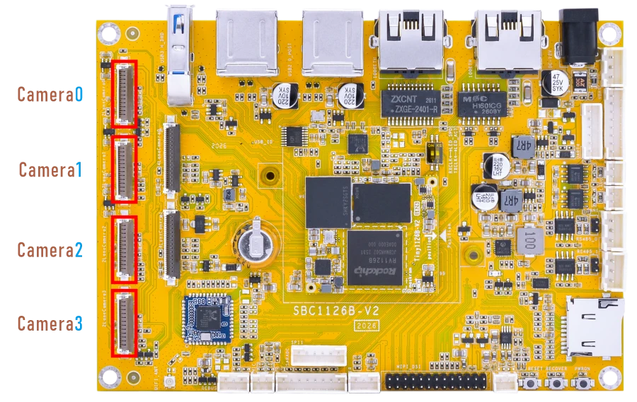
The SBC1126B provides six MIPI CSI camera interfaces, including four 2-lane MIPI CSI interfaces and two 4-lane MIPI CSI interfaces.
The 2-lane and 4-lane MIPI CSI camera modes are mutually exclusive and cannot be used simultaneously. Different camera modes require corresponding hardware configurations and firmware images.
The default camera sensors are as follows:
2-lane MIPI CSI camera: SC200AI.
4-lane MIPI CSI camera: IMX415.
To enable 4-lane cameras, remove the following resistors on the back side of the board:
Camera0: R5/R10/R11/R21/R22/R26/R31/R37/R39/R46
Camera1: R58/R60/R62/R63/R64/R65/R67/R68/R69/R70
4.16.1 2-lane Camera
4.16.1.1 GStreamer
❶ Connect the cameras to the board and power on.
❷ Check the camera preview device nodes.
1grep "" /sys/class/video4linux/v*/name | grep mainpath
root@rv1126b-buildroot:/# grep "" /sys/class/video4linux/v*/name | grep mainpath
/sys/class/video4linux/video44/name:rkisp_mainpath
/sys/class/video4linux/video52/name:rkisp_mainpath
/sys/class/video4linux/video60/name:rkisp_mainpath
/sys/class/video4linux/video68/name:rkisp_mainpath
❸ Preview camera.
1gst-launch-1.0 v4l2src device=/dev/video44 ! video/x-raw,format=NV16,width=1920,height=1080, framerate=25/1 ! waylandsink
root@rv1126b-buildroot:/# gst-launch-1.0 v4l2src device=/dev/video44 ! video/x-raw,format=NV16,width=1920,height=1080, framerate=25/1 ! waylandsink
mpp[1503]: mpp_info: mpp version: 958803d7 author: Herman Chen   2026-02-26 fix[h265d_rkv]: Fix rkv ref and poc setup overflow
mpp[1503]: mpp_info: mpp version: 958803d7 author: Herman Chen   2026-02-26 fix[h265d_rkv]: Fix rkv ref and poc setup overflow
mpp[1503]: mpp_info: mpp version: 958803d7 author: Herman Chen   2026-02-26 fix[h265d_rkv]: Fix rkv ref and poc setup overflow
mpp[1503]: mpp: unable to create enc vp8 for soc rv1126b unsupported
mpp[1503]: mpp_info: mpp version: 958803d7 author: Herman Chen   2026-02-26 fix[h265d_rkv]: Fix rkv ref and poc setup overflow
Setting pipeline to PAUSED ...
Using mplane plugin for capture
Pipeline is live and does not need PREROLL ...
Pipeline is PREROLLED ...
Setting pipeline to PLAYING ...
New clock: GstSystemClock
[   29.735171] rkisp_hw 21d00000.isp: set isp clk = 297000000Hz
[   29.737027] rkcif-mipi-lvds: stream[0] start streaming
[   29.737257] rockchip-mipi-csi2 mipi0-csi2: stream on, src_sd: 0000000080763734, sd_name:rockchip-csi2-dphy1
[   29.737274] rockchip-mipi-csi2 mipi0-csi2: stream ON
[   29.737316] rockchip-csi2-dphy1: dphy1, data_rate_mbps 742
[   29.737342] rockchip-csi2-dphy csi2-dphy1: csi2_dphy_s_stream stream on:1, dphy1, ret 0
[   29.737354] sc200ai 5-0030: 1920x1080@10, mode 0, vts 0x1a5e
Redistribute latency...
[06:43:35.126] seeing the first app
0:01:17.9 / 99:99:99.
1gst-launch-1.0 v4l2src device=/dev/video52 ! video/x-raw,format=NV16,width=1920,height=1080, framerate=25/1 ! waylandsink
1gst-launch-1.0 v4l2src device=/dev/video60 ! video/x-raw,format=NV16,width=1920,height=1080, framerate=25/1 ! kmssink
1gst-launch-1.0 v4l2src device=/dev/video68 ! video/x-raw,format=NV16,width=1920,height=1080, framerate=25/1 ! kmssink
1gst-launch-1.0 v4l2src device=/dev/video44 ! video/x-raw,format=NV16,width=480,height=320,framerate=25/1 ! videoconvert ! videoflip video-direction=90r ! videoconvert ! fpsdisplaysink name=video44 video-sink="waylandsink render-rectangle=\"<20,10,320,480>\"" &
2gst-launch-1.0 v4l2src device=/dev/video52 ! video/x-raw,format=NV16,width=480,height=320,framerate=25/1 ! videoconvert ! videoflip video-direction=90r ! videoconvert ! fpsdisplaysink name=video52 video-sink="waylandsink render-rectangle=\"<370,10,320,480>\"" &
3gst-launch-1.0 v4l2src device=/dev/video60 ! video/x-raw,format=NV16,width=480,height=320,framerate=25/1 ! videoconvert ! videoflip video-direction=90r ! videoconvert ! fpsdisplaysink name=video60 video-sink="waylandsink render-rectangle=\"<20,510,320,480>\"" &
4gst-launch-1.0 v4l2src device=/dev/video68 ! video/x-raw,format=NV16,width=480,height=320,framerate=25/1 ! videoconvert ! videoflip video-direction=90r ! videoconvert ! fpsdisplaysink name=video68 video-sink="waylandsink render-rectangle=\"<370,510,320,480>\"" &
4.16.1.2 Rockit
After the system boots, the stitched preview image from all four camera channels is displayed by default.
Four-Camera Preview
❶ Check the network status and obtain the Ethernet IP address of the board.
1ifconfig eth0
Serial terminal outputroot@rv1126b-buildroot:/# ifconfig eth0 Link encap:Ethernet HWaddr 4A:47:A5:18:57:64 inet addr:192.168.0.179 Bcast:192.168.0.255 Mask:255.255.255.0 inet6 addr: fe80::b466:2cb4:6ffb:2434/64 Scope:Link UP BROADCAST RUNNING MULTICAST MTU:1500 Metric:1 RX packets:17 errors:0 dropped:0 overruns:0 frame:0 TX packets:7 errors:0 dropped:0 overruns:0 carrier:0 collisions:0 txqueuelen:1000 RX bytes:1752 (1.7 KiB) TX bytes:858 (858.0 B) Interrupt:80
❷ Open VLC media player on the PC.

❸ Select Media -> Open Network Stream…
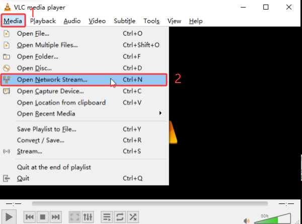
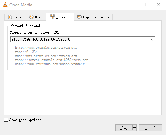
❹ Enter the following RTSP URL to preview the camera stream.
1rtsp://192.168.0.179:554/live/0
Note
Replace 192.168.0.179 with the actual Ethernet IP address of the board.
❺ Check the four-camera preview result.
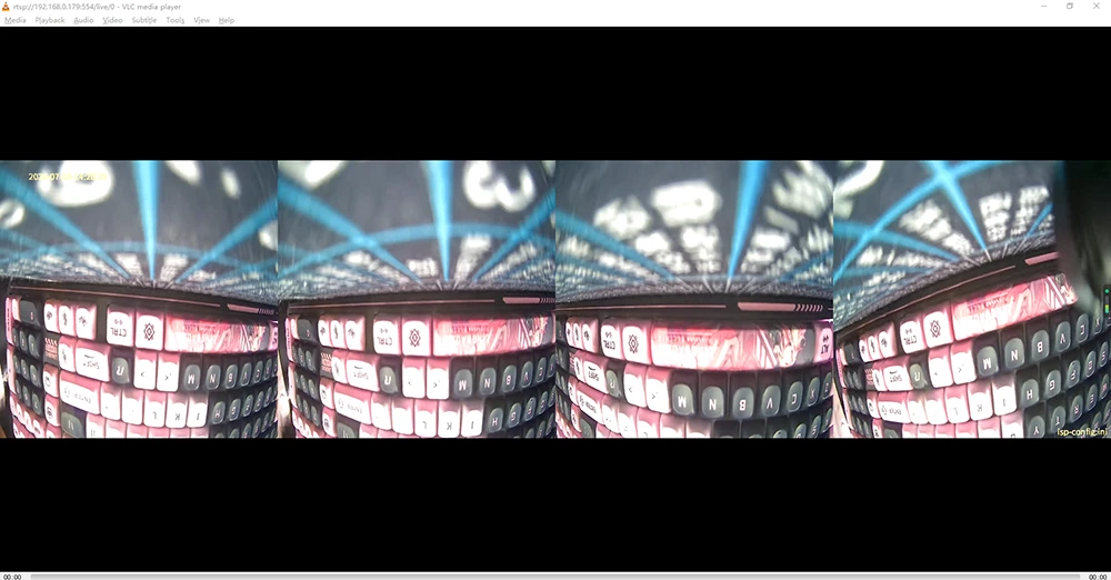
Single-Camera Preview
❶ Stop the default rkipc service.
1RkLunch-stop.sh
❷ Start the rkaiq_3A_server service.
1rkaiq_3A_server &
❸ Check the network status and obtain the Ethernet IP address of the board.
1ifconfig eth0
❹ Copy the streaming tool to the board.
1cp -rf /mnt/udisk/sample_demo_four_camera /usr/bin
2chmod +x /usr/bin/sample_demo_four_camera
❺ Start the four-channel camera demo.
1sample_demo_four_camera
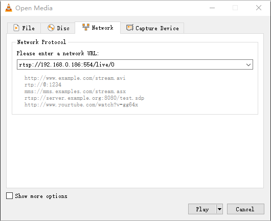
❻ Open VLC media player on the PC.
❼ Select Media -> Open Network Stream…
❽ Enter the RTSP URL to Preview the Camera Stream.
Camera01rtsp://192.168.0.186:554/live/0
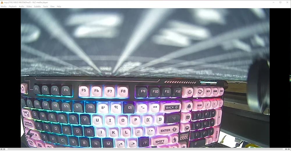 Camera1
1rtsp://192.168.0.186:554/live/2
Camera21rtsp://192.168.0.186:554/live/4
Camera31rtsp://192.168.0.186:554/live/6
Note
Replace 192.168.0.186 with the actual Ethernet IP address of the board.
4.16.2 4-lane Camera
Verify that the resistors on the back of the development board have been removed.
4.16.2.1 GStreamer
❶ Connect the cameras to the board and power on.
❷ Check the camera preview device nodes.
1grep "" /sys/class/video4linux/v*/name | grep mainpath
root@rv1126b-buildroot:/# grep "" /sys/class/video4linux/v*/name | grep mainpath
/sys/class/video4linux/video22/name:rkisp_mainpath
/sys/class/video4linux/video30/name:rkisp_mainpath
❸ Preview camera.
1gst-launch-1.0 v4l2src device=/dev/video22 ! video/x-raw,format=NV16,width=1920,height=1080, framerate=25/1 ! kmssink
1gst-launch-1.0 v4l2src device=/dev/video30 ! video/x-raw,format=NV16,width=1920,height=1080, framerate=25/1 ! kmssink
4.16.2.2 Rockit
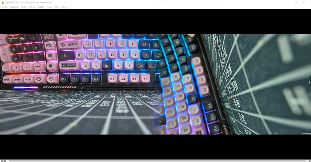
After the system boots, the stitched preview image from the two camera channels is displayed by default on the screen.
Dual-Camera Preview
❶ Check the network status and obtain the Ethernet IP address of the board.
1ifconfig eth0
❷ Open VLC media player on the PC.
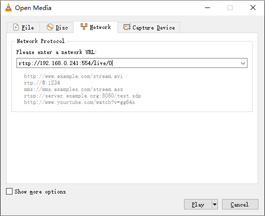
❸ Select Media -> Open Network Stream…
❹ Enter the following RTSP URL to preview the camera stream.
1rtsp://192.168.0.241:554/live/0
Note
Replace 192.168.0.241 with the actual Ethernet IP address of the board.
Single-Camera Preview
❶ Stop the default rkipc service.
1RkLunch-stop.sh
❷ Start the rkaiq_3A_server service.
1rkaiq_3A_server &
❸ Check the network status and obtain the Ethernet IP address of the board.
1ifconfig eth0
root@rv1126b-buildroot:/# ifconfig eth0
eth0      Link encap:Ethernet  HWaddr 2E:E2:A3:3D:3C:0B
          inet addr:192.168.0.241  Bcast:192.168.0.255  Mask:255.255.255.0
          inet6 addr: fe80::bfea:46f2:bca1:ae31/64 Scope:Link
          UP BROADCAST RUNNING MULTICAST  MTU:1500  Metric:1
          RX packets:511 errors:0 dropped:1 overruns:0 frame:0
          TX packets:73 errors:0 dropped:0 overruns:0 carrier:0
          collisions:0 txqueuelen:1000
          RX bytes:47184 (46.0 KiB)  TX bytes:7350 (7.1 KiB)
          Interrupt:80
❹ SStart the dual-camera RTSP streaming service.
1sample_demo_dual_camera -s 0 -W 1920 -H 1080 -w 720 -h 576 -f 30 -r 0 -s 1 -W 1920 -H 1080 -w 720 -h 576 -f 30 -r 0 -n 0 -b 1
❺ Open VLC media player on the PC.
❻ Select Media -> Open Network Stream…
❼ Enter the RTSP URL to Preview the Camera Stream.
Camera01rtsp://192.168.0.241:554/live/0
Camera11rtsp://192.168.0.241:554/live/2
4.17 Video Playback
4.17.1 GStreamer
4.17.1.1 Built-in Script
The script instruction directory is in /rockchip-test/video/, just run it.
root@rv1126b-buildroot:/# /rockchip-test/video/test_gst_video.sh
Setting pipeline to PAUSED ...
Pipeline is PREROLLING ...
Redistribute latency...
mpp[1489]: mpp_info: mpp version: 958803d7 author: Herman Chen   2026-02-26 fix[h265d_rkv]: Fix rkv ref and poc setup overflow
mpp[1489]: mpp_info: mpp version: 958803d7 author: Herman Chen   2026-02-26 fix[h265d_rkv]: Fix rkv ref and poc setup overflow
mpp[1489]: mpp_info: mpp version: 958803d7 author: Herman Chen   2026-02-26 fix[h265d_rkv]: Fix rkv ref and poc setup overflow
mpp[1489]: mpp: unable to create enc vp8 for soc rv1126b unsupported
mpp[1489]: mpp_info: mpp version: 958803d7 author: Herman Chen   2026-02-26 fix[h265d_rkv]: Fix rkv ref and poc setup overflow
mpp[1489]: mpp_info: mpp version: 958803d7 author: Herman Chen   2026-02-26 fix[h265d_rkv]: Fix rkv ref and poc setup overflow
Redistribute latency...
mpp[1489]: h264d_api: is_avcC=1
mpp[1489]: mpp_buf_slot: mismatch h_stride_by_pixel 1472 - 1280
mpp[1489]: mpp_buf_slot: mismatch h_stride_by_byte 1472 - 1280
mpp[1489]: mpp_buf_slot: mismatch size_total 1589760 - 1843200
mpp[1489]: mpp_buf_slot: mismatch h_stride_by_pixel 1472 - 1280
mpp[1489]: mpp_buf_slot: mismatch h_stride_by_byte 1472 - 1280
mpp[1489]: mpp_buf_slot: mismatch size_total 1589760 - 1843200
Pipeline is PREROLLED ...0 %)
Prerolled, waiting for async message to finish...
Setting pipeline to PLAYING ...
Redistribute latency...
New clock: GstSystemClock
0:00:03.2 / 0:00:29.5 (10.9 %)
4.17.1.2 Command Line
1export GST_MPP_VIDEODEC_DEFAULT_ARM_AFBC=1
2gst-play-1.0 --videosink="waylandsink fullscreen=true" /mnt/udisk1/video/4KP30/4K30P-BLACKPINK-DDU-DU_DDU-DU.mp4 --audiosink="alsasink device=hw:0,0"
Command explanation
export GST_MPP_VIDEODEC_DEFAULT_ARM_AFBC=1: Open AFBC.--videosink="kmssink plane-id=74": Specifies the plane. Which can be viewed using the command cat /sys/kernel/debug/dri/0/state | grep “plane[”/mnt/udisk1/video/4KP30/4K30P-BLACKPINK-DDU-DU_DDU-DU.mp4: The media file path to be played.--audiosink="alsasink device=hw:0,0": Specifies the audio output device as hw:0,0.
root@rv1126b-buildroot:/# export GST_MPP_VIDEODEC_DEFAULT_ARM_AFBC=1
root@rv1126b-buildroot:/#
 device=hw:0,0"deo/4KP30/4K30P-BLACKPINK-DDU-DU_DDU-DU.mp4 --audiosink="alsasink
Press 'k' to see a list of keyboard shortcuts.
Now playing /mnt/udisk1/video/4KP30/4K30P-BLACKPINK-DDU-DU_DDU-DU.mp4
Redistribute latency...
Redistribute latency...
mpp[1553]: mpp_info: mpp version: 958803d7 author: Herman Chen   2026-02-26 fix[h265d_rkv]: Fix rkv ref and poc setup overflow
mpp[1553]: mpp_info: mpp version: 958803d7 author: Herman Chen   2026-02-26 fix[h265d_rkv]: Fix rkv ref and poc setup overflow
mpp[1553]: mpp_info: mpp version: 958803d7 author: Herman Chen   2026-02-26 fix[h265d_rkv]: Fix rkv ref and poc setup overflow
mpp[1553]: mpp: unable to create enc vp8 for soc rv1126b unsupported
mpp[1553]: mpp_info: mpp version: 958803d7 author: Herman Chen   2026-02-26 fix[h265d_rkv]: Fix rkv ref and poc setup overflow
mpp[1553]: mpp_info: mpp version: 958803d7 author: Herman Chen   2026-02-26 fix[h265d_rkv]: Fix rkv ref and poc setup overflow
Redistribute latency...
Redistribute latency...
mpp[1553]: h264d_api: is_avcC=1
mpp[1553]: mpp_buf_slot: mismatch h_stride_by_pixel 4032 - 3840
mpp[1553]: mpp_buf_slot: mismatch h_stride_by_byte 4032 - 3840
mpp[1553]: mpp_buf_slot: mismatch size_total 13063680 - 16588800
mpp[1553]: mpp_buf_slot: mismatch h_stride_by_pixel 4032 - 3840
mpp[1553]: mpp_buf_slot: mismatch h_stride_by_byte 4032 - 3840
mpp[1553]: mpp_buf_slot: mismatch size_total 13063680 - 16588800
Redistribute latency...
[08:23:02.993] seeing the first app
0:00:10.6 / 0:03:28.8
4.17.2 Rockit
❶ Stop the default rkipc service.
1RkLunch-stop.sh
❷ Run the simple_vdec_bind_vo command to play video.
1simple_vdec_bind_vo -i /mnt/udisk/testh264.h264
Command explanation
simple_vdec_bind_vo: Video decoding and display test tool.-i: Specifies the input video file./mnt/udisk/testh264.h264: Input H.264 file path.
Note
This command supports H.264 elementary stream files, such as .h264 files. Standard MP4 files are not supported.